
Experimental Study on Seismic Performance of Built-in Straw Rope Reinforced Load-bearing Rammed Earth Wall
-
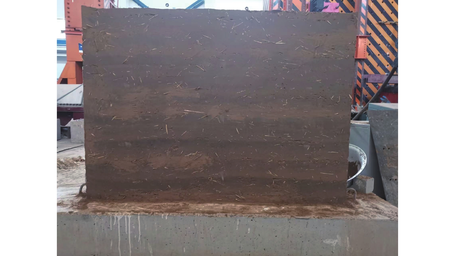
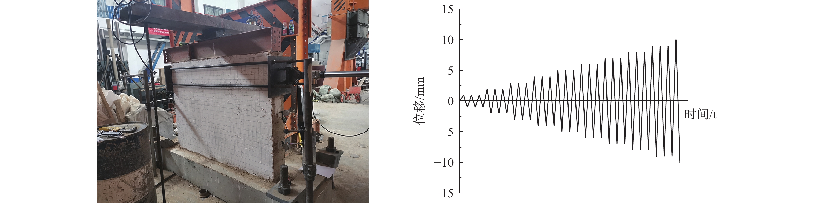
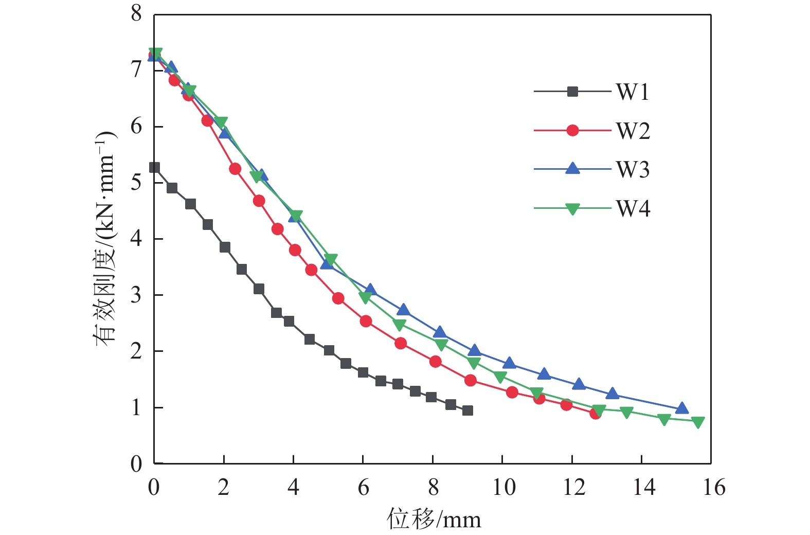
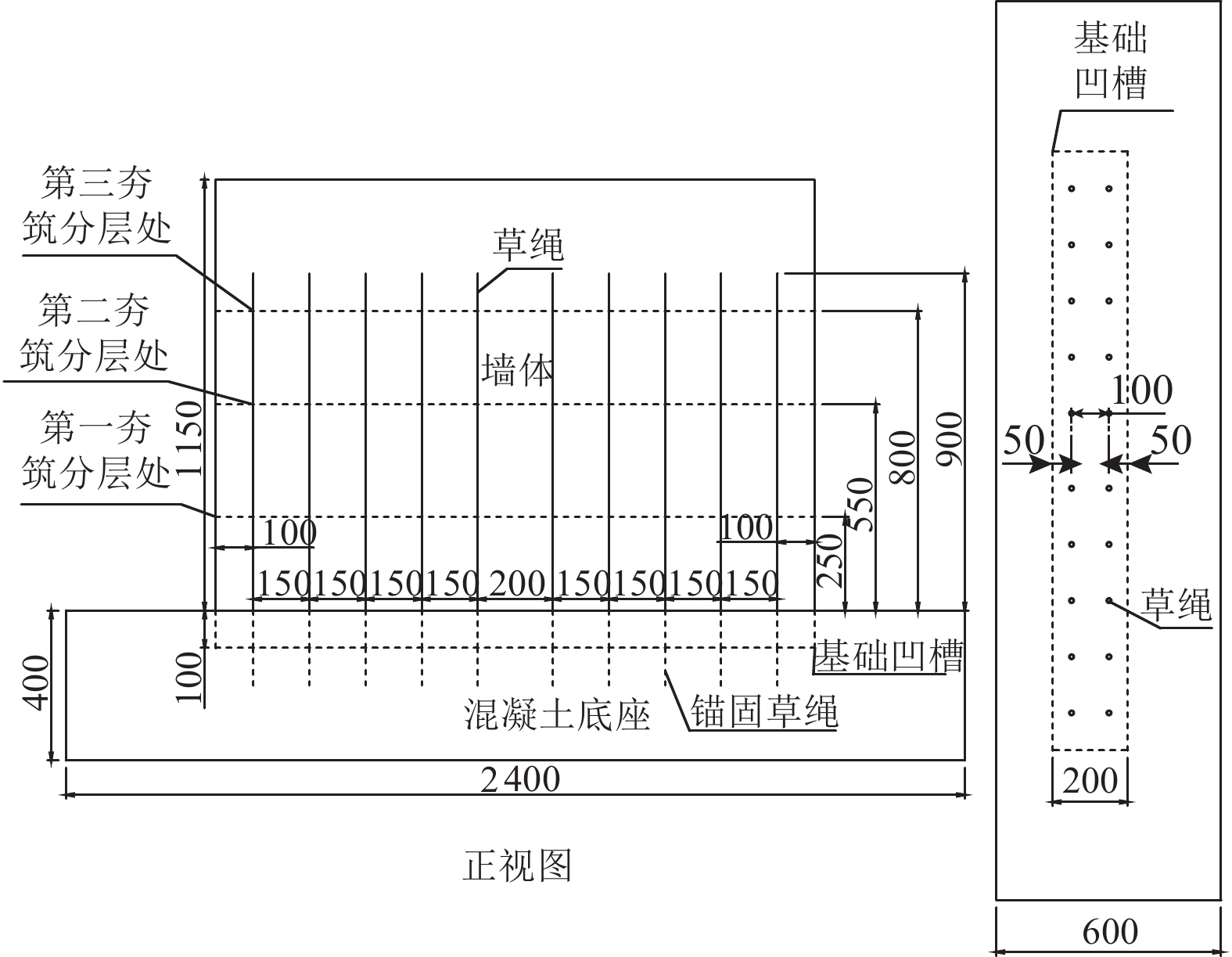
摘要: 为了解决夯土墙体夯筑分层处受力薄弱的问题,本文提出一种内置草绳增强承重夯土墙体性能的方法,以草绳含量及埋置高度为变量,对4片夯土墙体1/3缩尺模型进行拟静力试验,探究其破坏形态、承载及变形能力、耗能能力、刚度退化等抗震性能。试验结果表明:内置草绳可提高墙体各夯筑层间粘结性,延缓夯筑分层处水平裂缝的开展及贯通,从而提高墙体整体性,此外其对墙体承载能力、变形能力均有提升,且提升率与草绳高度呈正相关,二者分别提升108.3%和35.6%;内置草绳的墙体试件滞回曲线更为饱满,达到破坏荷载时,其等效黏滞阻尼系数在0.16~0.23之间,同时初始刚度较无草绳墙体提升40%,且加载过程中刚度始终高于无草绳墙体。实际应用中,建议内置草绳高度应超过1/2墙高。研究成果可对夯土建筑的抗震设计及应用推广提供参考依据。Abstract: In order to solve the problem of weak stress at the rammed layer of rammed earth wall, a load-bearing rammed earth wall reinforced by built-in grass rope is proposed. Taking the grass rope content and embedded height as variables, in order to explore the seismic performance of the wall, such as failure mode, bearing capacity, deformation capacity, energy dissipation capacity and stiffness degradation, a quasi-static test was carried out on four rammed earth walls with scale ratio being 1/3. The test results show that the built-in grass rope can improve the adhesion between the rammed layers of the wall, delay the development and penetration of the horizontal cracks at the rammed layers, and thus improve the integrity of the wall; In addition, the bearing capacity and deformation capacity of the wall are improved, and the lifting rate is positively correlated with the height of the grass rope, which is increased by 108.3% and 35.6% respectively; The hysteresis curve of the wall specimen with built-in grass rope is fuller than that of the wall specimen without grass rope. When the failure load is reached, the equivalent viscous damping coefficient is between 0.16 and 0.23, and the initial stiffness is 40% higher than that of the wall without grass rope. In practical applications, it is recommended that the height of the built-in grass rope should exceed 1/2 wall height. The research results can provide reference for seismic design and application of rammed earth buildings.
-
Key words:
- Raw soil structure /
- Rammed earth wall /
- Quasi-static test /
- Seismic performance
-
表 1 试件方案设计表
Table 1. Sample scheme design table
试件编号 生土掺料 草绳高度/mm 草绳/
墙高W1 0.8%麦秸秆 无 无 W2 0.8%麦秸秆 300 1/4 W3 0.8%麦秸秆 600 1/2 W4 0.8%麦秸秆 900 3/4  下载: 导出CSV
表 2 各试件特征点处力学性能参数
Table 2. Mechanical property parameters at characteristic points of each specimen
试件编号 屈服位移
/mm屈服荷载
/kN峰值位移
/mm峰值荷载
/kN极限位移
/mm极限荷载
/kN延性系数 W1 3.73 9.20 5.02 10.10 9.50 8.40 2.27 W2 3.90 13.80 7.90 17.70 11.10 11.20 2.80 W3 3.88 17.37 7.04 19.51 12.76 16.42 3.28 W4 3.92 17.40 6.12 21.04 12.89 17.58 3.28
下载: 导出CSV
表 3 特征点处等效黏滞阻尼系数
Table 3. Equivalent viscous damping coefficient at characteristic points
试件编号 开裂荷载阻尼系数 屈服荷载阻尼系数 极限荷载阻尼系数 破坏荷载阻尼系数 W1 0.0744 0.0865 0.0982 0.1145 W2 0.0811 0.1125 0.1410 0.1687 W3 0.0902 0.1236 0.1665 0.2058 W4 0.0948 0.1358 0.1796 0.2243
下载: 导出CSV
-
陈忠范, 郑怡, 沈小俊等, 2012. 村镇生土结构建筑抗震技术手册. 南京: 东南大学出版社. 和法国, 吕燃, 粟华忠等, 2019. SH材料加固夯筑遗址土耐久性试验及机理研究. 岩土力学, 40(S1): 297—307He F. G. , Lü R. , Su H. Z. , et al. , 2019. Durability test and reinforced mechanism on adding SH materials into soil of archaeological sites. Rock and Soil Mechanics, 40(S1): 297—307. (in Chinese) 李志华, 周明卿, 陈伟康等, 2016. 加筋夯土墙片的平面内抗剪性能试验. 中南大学学报(自然科学版), 47(8): 2835—2841Li Z. H. , Zhou M. Q. , Chen W. K. , et al. , 2016. Experimental investigation on in-plane shear behavior of reinforced rammed earth panels. Journal of Central South University (Science and Technology), 47(8): 2835—2841. (in Chinese) 蔺广涵, 叶洪东, 2018. 棉花秸秆改性生土材料试验研究. 天津城建大学学报, 24(3): 196—199 doi: 10.19479/j.2095-719x.1803196Lin G. H. , Ye H. D. , 2018. Experimental research on raw soil materials modified by cotton straw. Journal of Tianjin Chengjian University, 24(3): 196—199. (in Chinese) doi: 10.19479/j.2095-719x.1803196 刘蕾, 姚勇, 张玲玲, 2021. 改性夯土墙材的强度影响因素相关性研究. 硅酸盐通报, 40(4): 1286—1295 doi: 10.16552/j.cnki.issn1001-1625.2021.04.027Liu L. , Yao Y. , Zhang L. L. , 2021. Correlation of strength influencing factors of modified rammed earth wall materials. Bulletin of the Chinese Ceramic Society, 40(4): 1286—1295. (in Chinese) doi: 10.16552/j.cnki.issn1001-1625.2021.04.027 刘强, 童丽萍, 许启铿, 2018. 带竖向销键夯土墙抗震性能试验. 建筑科学与工程学报, 35(3): 79—86Liu Q. , Tong L. P. , Xu Q. K. , 2018. Experiment on seismic performance of rammed earth wall with vertical pin. Journal of Architecture and Civil Engineering, 35(3): 79—86. (in Chinese) 卢家成, 刘嘉良, 李威翰等, 2020. 生土建筑与材料研究现状. 材料导报, 34(S2): 269—272Lu J. C. , Liu J. L. , Li W. H. , et al. , 2020. Research status of raw soil building and materials. Materials Reports, 34(S2): 269—272. (in Chinese) 王兰民, 王强, 2011. 西北地区农村民房现状及抗震技术研究. 华南地震, 31(4): 14—22 doi: 10.13512/j.hndz.2011.04.001Wang L. M. , Wang Q. , 2011. Study on status and anti-seismic technology of rural houses in Northwest China. South China Journal of Seismology, 31(4): 14—22. (in Chinese) doi: 10.13512/j.hndz.2011.04.001 王毅红, 梁楗, 张项英等, 2015. 我国生土结构研究综述. 土木工程学报, 48(5): 98—107Wang Y. H. , Liang J. , Zhang X. Y. , et al. , 2015. Review of raw-soil structure in China. China Civil Engineering Journal, 48(5): 98—107. (in Chinese) 王赟, 冯映雪, 张波等, 2021. 竹片网水泥砂浆加固承重夯土墙体抗震试验研究. 世界地震工程, 37(3): 104—110Wang Y. , Feng Y. X. , Zhang B. , et al. , 2021. Experimental study on seismic performance of bamboo mesh and cement mortar reinforced rammed earth wall. World Earthquake Engineering, 37(3): 104—110. (in Chinese) 徐舜华, 王兰民, 王强等, 2011. 甘肃武都典型夯土民房承重墙体抗剪强度试验研究. 西北地震学报, 33(4): 354—358, 385Xu S. H. , Wang L. M. , Wang Q. , et al. , 2011. Experimental study on shearing strength of typical rammed earth wall in Wudu area, Gansu Province. Northwestern Seismological Journal, 33(4): 354—358, 385. (in Chinese) 张琰鑫, 童丽萍, 2012. 夯土住宅结构性能分析及加固方法. 世界地震工程, 28(2): 72—78Zhang Y. X. , Tong L. P. , 2012. Performance analysis and strengthening method of rammed earth buildings. World Earthquake Engineering, 28(2): 72—78. (in Chinese) 张又超, 王毅红, 张项英等, 2015. 单面钢丝网水泥砂浆加固承重夯土墙体抗震试验研究. 西安建筑科技大学学报(自然科学版), 47(2): 255—259Zhang Y. C. , Wang Y. H. , Zhang X. Y. , et al. , 2015. Experimental study on strengthening rammed-earth wall with single side ferro-cement surface layer. Journal of Xi'an University of Architecture & Technology (Natural Science Edition), 47(2): 255—259. (in Chinese) 中华人民共和国住房和城乡建设部, 2008. JGJ 161—2008 镇(乡)村建筑抗震技术规程. 北京: 中国建筑工业出版社.Ministry of Housing and Urban-Rural Development of the People's Republic of China, 2008. JGJ 161—2008 Seismic technical specification for building construction in town and village. Beijing: China Architecture & Building Press. (in Chinese) 中华人民共和国住房和城乡建设部, 2015. JGJ/T 101—2015 建筑抗震试验规程. 北京: 中国建筑工业出版社.Ministry of Housing and Urban-Rural Development of the People's Republic of China, 2015. JGJ/T 101—2015 Specification for seismic test of buildings. Beijing: China Architecture & Building Press. (in Chinese) 周铁钢, 段文强, 穆钧等, 2013. 全国生土农房现状调查与抗震性能统计分析. 西安建筑科技大学学报(自然科学版), 45(4): 487—492Zhou T. G. , Duan W. Q. , Mu J. , et al. , 2013 a. Statistical analysis and survey on the aseismatic performance of theraw-soil building status in China's rural areas. Journal of Xi'an University of Architecture & Technology (Natural Science Edition), 45(4): 487—492. (in Chinese) Arslan M. E. , Emiroğlu M. , Yalama A. , 2017. Structural behavior of rammed earth walls under lateral cyclic loading: a comparative experimental study. Construction and Building Materials, 133: 433—442. doi: 10.1016/j.conbuildmat.2016.12.093 ASTM, 2007. ASTM E2126—07 a Standard test methods for cyclic (reversed) load test for shear resistance of vertical elements of the lateral force resisting systems for buildings. West Conshohocken: ASTM International. Jové-Sandoval F. , Barbero-Barrera M. M. , Flores Medina N. , 2018. Assessment of the mechanical performance of three varieties of pine needles as natural reinforcement of adobe. Construction and Building Materials, 187: 205—213. doi: 10.1016/j.conbuildmat.2018.07.187 Karanikoloudis G. , Lourenço P. B. , 2018. Structural assessment and seismic vulnerability of earthen historic structures. Application of sophisticated numerical and simple analytical models. Engineering Structures, 160: 488—509. Miccoli L. , Müller U. , Pospíšil S. , 2017. Rammed earth walls strengthened with polyester fabric strips: experimental analysis under in-plane cyclic loading. Construction and Building Materials, 149: 29—36. doi: 10.1016/j.conbuildmat.2017.05.115 Prabakar J. , Sridhar R. S. , 2002. Effect of random inclusion of sisal fibre on strength behaviour of soil. Construction and Building Materials, 16(2): 123—131. doi: 10.1016/S0950-0618(02)00008-9 -


 点击查看大图
图(7) / 表(3)
计量
- 文章访问数: 138
- HTML全文浏览量: 40
- PDF下载量: 7
- 被引次数: 0
