
Seismic Analysis of Single-arch and Large-span Subway Station Structure under Bidirectional Ground Motion
-
摘要: 地铁车站结构作为现代城市交通工程的重要组成部分,其抗震问题已成为城市工程抗震和防灾减灾研究的重点与难点。以深圳地铁3号线四期低碳城单拱大跨车站为研究对象,采用近场波动有限元方法,建立三维土-结构相互作用整体有限元分析模型。选取3条人工波和3条天然波作为输入地震动,分析水平单向地震动、水平与竖向双向地震动作用下单拱大跨地铁车站结构三维地震响应规律。研究结果表明,双向地震动作用下单拱大跨无柱结构及矩形框架有柱结构的水平位移及层间位移均略小于单向地震动作用下,但矩形框架有柱结构在竖向地震动作用下的中柱轴压比明显增加,说明单拱大跨车站结构可有效降低双向地震动作用下中柱轴压比变大的风险;双向地震动作用下的结构峰值弯矩大于单向地震动作用下,说明进行结构设计时应适当考虑竖向地震动作用的影响;单拱大跨无柱结构拱顶弯矩明显小于矩形框架有柱结构顶板跨中弯矩,改善了常规矩形框架结构顶板受力性能,但由于单拱大跨无柱结构缺少中柱竖向支撑作用,其底板及侧墙底部弯矩明显大于矩形框架有柱结构,尤其在双向地震动作用下更明显,因此单拱大跨无柱结构需加强底板及侧墙的厚度与配筋,以抵抗较大的弯矩响应。Abstract: As subway being an important part of modern urban transport engineering, the earthquake resistance of subway station structure has become the key and difficult point in the research of earthquake resistance and disaster prevention and reduction of urban engineering. In this paper, a three-dimensional finite element model of soil-structure interaction for a single-arch long-span structure in the fourth phase of Shenzhen Metro Line 3 is established by using the near-field wave finite element method. Three artificial waves and three natural waves were selected as input ground motions to analyse the three-dimensional seismic response of the single-arch and large-span subway station structures under horizontal unidirectional ground motions and horizontal and vertical bi-directional ground motions. The numerical results show that the horizontal displacement and interstory displacement of single-arch long-span column-free structure and rectangular frame column-free structure under bi-directional earthquake are slightly less than those under unidirectional earthquake. However, the axial compression ratio of the columns in the rectangular frame structure increases obviously under the action of the vertical seismic motion, which indicates that the single-arch and long-span station structure can effectively avoid the risk of the increase of the axial compression ratio of the columns under the action of bi-directional ground motions; The peak moment of structure is larger than that of the structure under the action of bi-directional ground motions, which indicates that the effect of vertical earthquake motion should be considered in the structure design; The bending moment of the single-arch and large-span column-free structure is obviously smaller than that of the rectangular frame with columns, which improves the mechanical behaviour of the roof of the conventional rectangular frame structure. However, the bending moment of the bottom plate and the bottom of the side wall is obviously larger than that of the column structure of the rectangular frame, especially under the action of bi-directional ground motions. Therefore, it is necessary to strengthen the thickness and reinforcement of the soleplate and the side wall of the single arch long-span column-free structure to resist the large moment response.1)
1 1 李洋,2018. 浅埋地下框架结构地震破坏机理研究. 北京:北京工业大学. -

图 6 人工波相应反应谱对目标谱的拟合曲线
Figure 6. The fitting of the corresponding response spectrum of artificial wave to the target spectrum
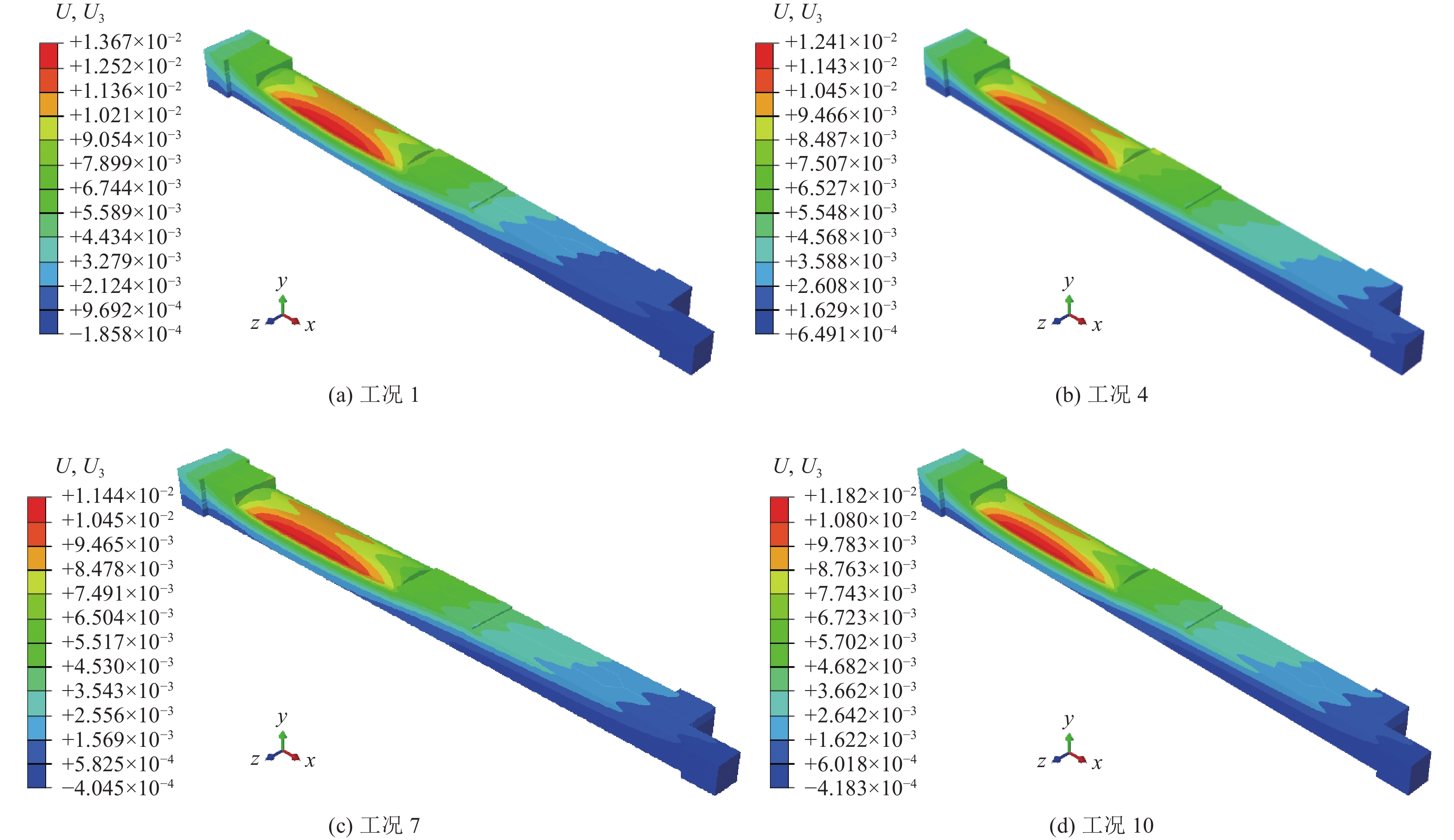
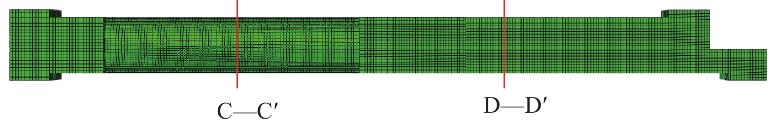
图 8 地铁车站结构最大水平位移时刻结构变形云图(单位:米)
Figure 8. Cloud diagram at the moment of maximum horizontal displacement of subway station structure (Unit: m)
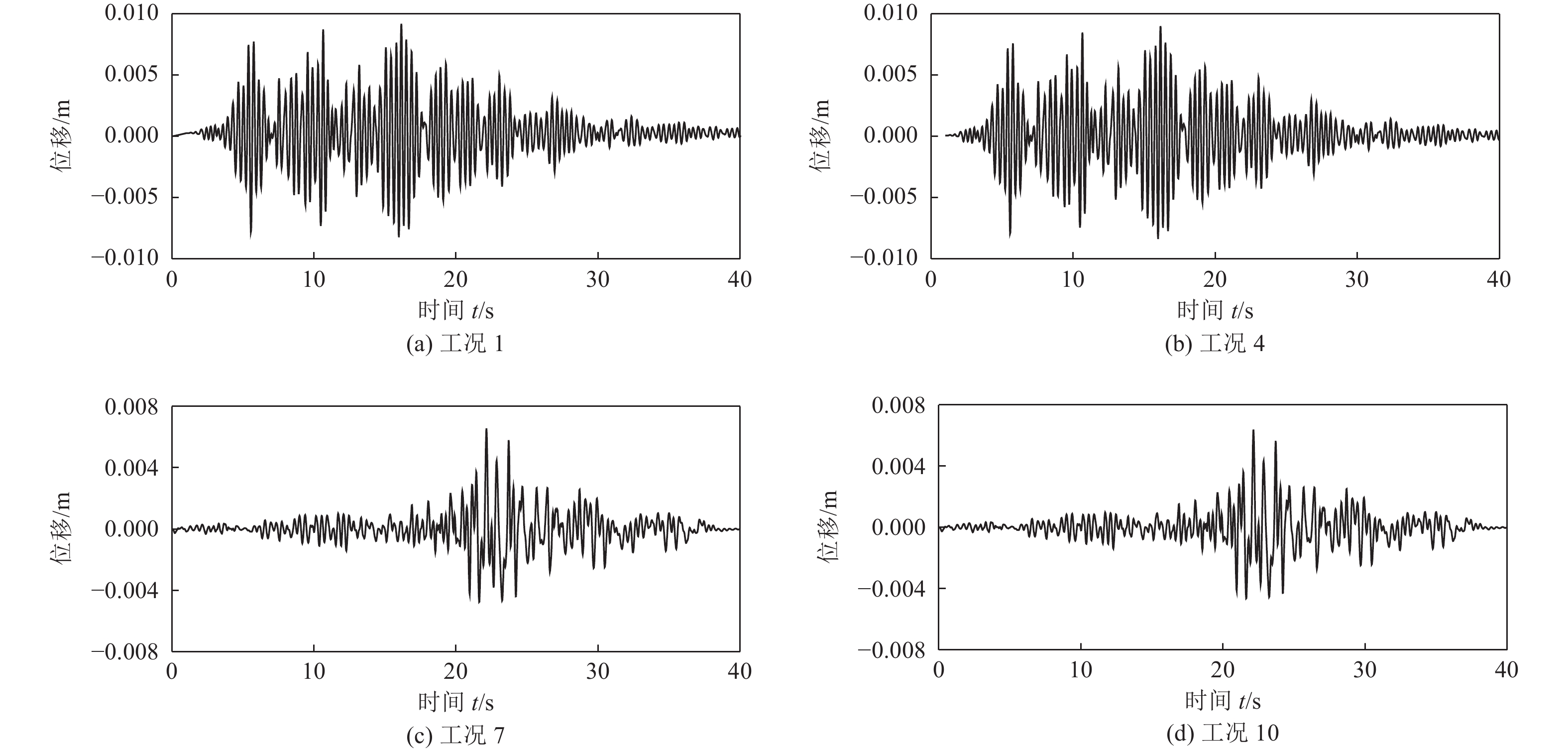
图 9 C—C′断面顶、底板相对位移时程曲线
Figure 9. Relative displacement time history of the top and bottom plates of the C—C′ section
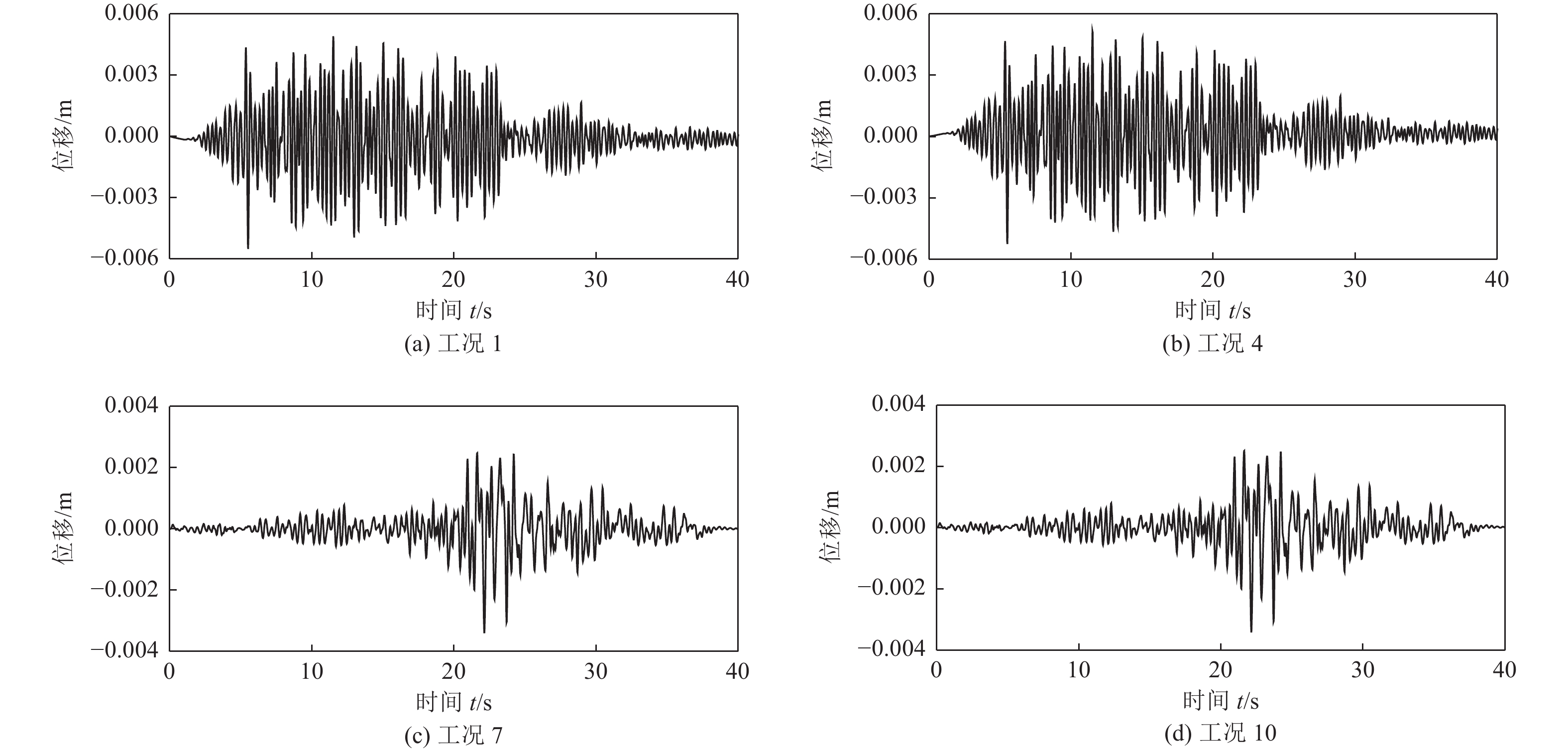
图 10 D—D′断面顶、底板相对位移时程
Figure 10. Relative displacement time history of the top and bottom plates of the D—D′ section
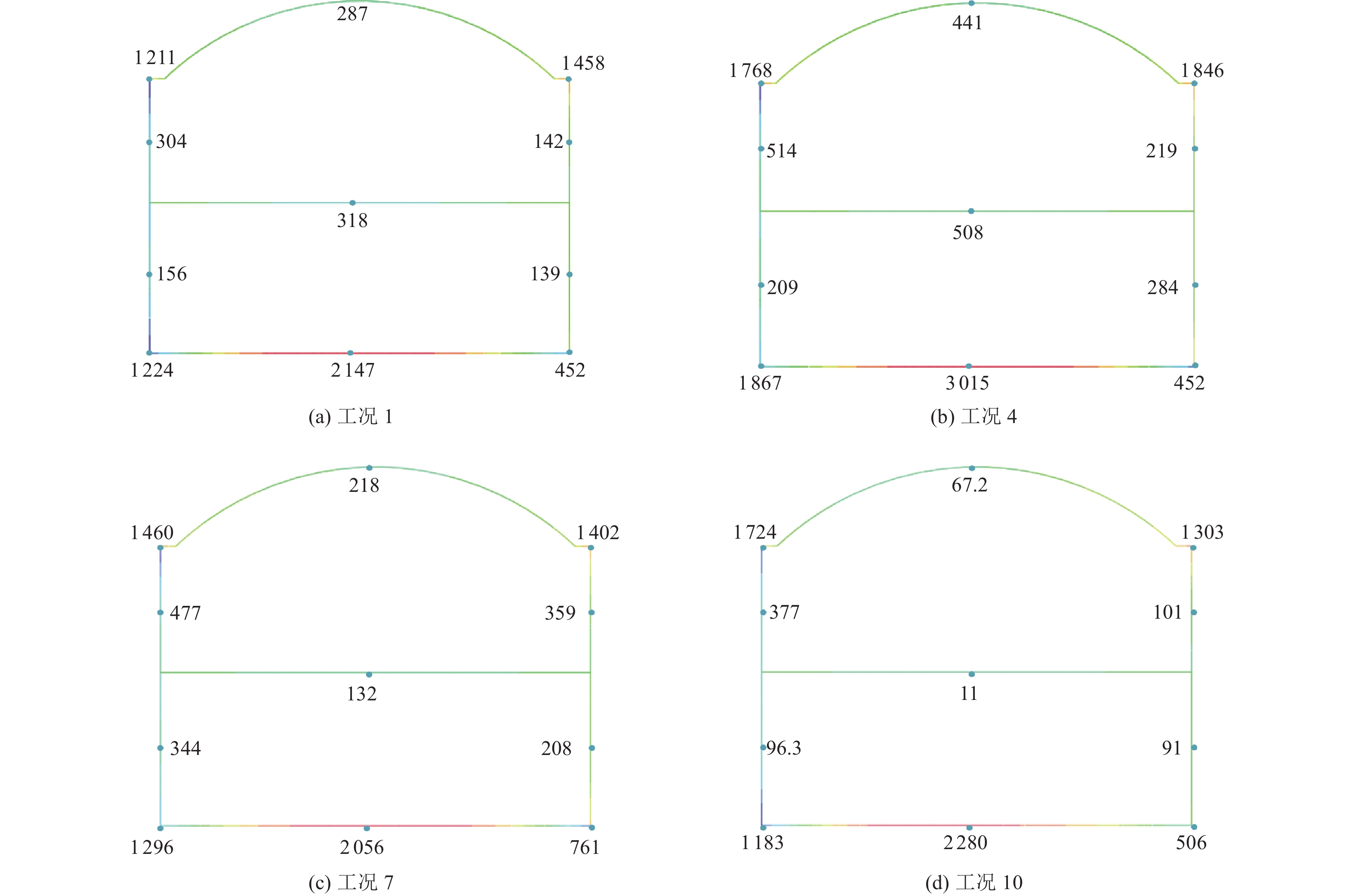
图 11 C—C′断面弯矩云图(单位:千牛·米)
Figure 11. Bending moment cloud diagram of C—C′ section(Unit:kN·m)

图 12 D—D′断面弯矩云图(单位:千牛·米)
Figure 12. Bending moment cloud diagram of D—D′ section(Unit:kN·m)

图 13 车站柱网轴力云图(单位:牛)
Figure 13. Axial force cloud diagram of column grid in station(Unit: N)
表 1 场地土物理参数
Table 1. Physical parameters of ground soil
层号 土层描述 层厚/m 密度/(g·cm−3) 剪切波速/(m·s−1) 泊松比 1 素填土 2.4 1.90 155.0 0.35 2 粉质黏土 6.4 1.92 220.8 0.35 3 砂质黏性土 5.4 1.95 282.4 0.28 4 全风化花岗岩 8.2 1.97 362.0 0.33 5 强风化花岗岩 13.1 2.10 470.6 0.25  下载: 导出CSV
表 2 土层模量比和阻尼比
Table 2. Modulus ratio and damping ratio of soil layer
土类 参数 剪应变γ/10−4 0.05 0.1 0.5 1 5 10 50 100 素填土 $ G/{G_{\max }} $ 0.960 0 0.950 0 0.800 0 0.700 0 0.300 0 0.200 0 0.150 0 0.100 0 $ \lambda $ 0.025 0 0.028 0 0.030 0 0.035 0 0.080 0 0.100 0 0.110 0 0.120 0 粉质黏土 $ G/{G_{\max }} $ 0.995 0 0.988 0 0.939 0 0.876 0 0.572 0 0.401 0 0.145 0 0.075 0 $ \lambda $ 0.015 0 0.026 0 0.043 0 0.044 0 0.069 0 0.074 0 0.094 0 0.098 0 砂质黏性土 $ G/{G_{\max }} $ 0.996 2 0.910 0 0.964 0 0.931 3 0.737 3 0.593 6 0.236 7 0.138 0 $ \lambda $ 0.012 0 0.015 9 0.030 1 0.039 3 0.068 8 0.082 6 0.106 0 0.110 9 全、强风化岩 $ G/{G_{\max }} $ 0.990 0 0.970 0 0.900 0 0.850 0 0.700 0 0.550 0 0.320 0 0.200 0 $ \lambda $ 0.004 0 0.006 0 0.019 0 0.030 0 0.075 0 0.090 0 0.110 0 0.120 0
下载: 导出CSV
表 3 车站结构变形
Table 3. The deformation of the station structural
工况 结构最大水平位移/mm C—C′断面 D—D′断面 位移差/mm 位移角 位移差/mm 位移角 1 13.6 9.18 1/1 810 5.52 1/3 011 2 11.4 7.79 1/2 134 5.38 1/3 089 3 13.6 10.54 1/1 577 7.45 1/2 231 4 12.4 8.99 1/1 849 5.28 1/3 148 5 11.7 7.66 1/2 170 5.12 1/3 246 6 13.9 9.23 1/1 801 6.89 1/2 412 7 11.4 6.57 1/2 530 2.48 1/6 702 8 12.5 7.12 1/2 334 3.57 1/4 655 9 11.2 6.42 1/2 589 2.47 1/6 729 10 11.8 6.39 1/2 601 2.25 1/7 387 11 12.1 6.83 1/2 433 3.12 1/5 327 12 11.6 6.25 1/2 659 2.08 1/7 990
下载: 导出CSV
表 4 车站结构标准断面弯矩
Table 4. Bending moment of standard section at station structure
工况 C—C′断面/(kN·m) D—D′断面/(kN·m) 拱顶 拱底 侧墙(左) 拱顶 拱底 侧墙(左) 1 287 2 147 1 211 371 1 192 589 2 298 2 334 1 275 406 1 223 594 3 322 2 561 1 390 465 1 373 619 4 441 3 015 1 768 583 1 636 654 5 467 2 994 1 638 591 1 669 668 6 481 3 269 1 841 621 1 791 709 7 218 2 056 1 460 297 1 118 570 8 341 2 589 1 648 331 1 325 651 9 235 2 152 1 463 285 1 211 581 10 67.2 2 280 1 724 223 1 258 344 11 92 2 558 1 889 371 1 568 473 12 74 2 317 1 759 245 1 301 371
下载: 导出CSV
表 5 车站结构柱网最大轴力及轴压比
Table 5. Maximum axial force and axial compression ratio of station structural column network
工况 最大轴力/kN 最大轴压比 工况 最大轴力/kN 最大轴压比 1 11 421 0.618 7 10 513 0.569 2 11 060 0.598 8 10 947 0.592 3 11 380 0.616 9 10 695 0.597 4 11 504 0.622 10 12 271 0.664 5 11 145 0.603 11 12 341 0.668 6 11 393 0.616 12 12 314 0.666
下载: 导出CSV
-
杜修力, 赵密, 王进廷, 2006. 近场波动模拟的人工应力边界条件. 力学学报, 38(1): 49—56Du X. L. , Zhao M. , Wang J. T. , 2006. A stress artificial boundary in Fea for near-field wave problem. Chinese Journal of Theoretical and Applied Mechanics, 38(1): 49—56. (in Chinese) 杜修力, 马超, 路德春等, 2017. 大开地铁车站地震破坏模拟与机理分析. 土木工程学报, 50(1): 53—62, 69Du X. L. , Ma C. , Lu D. C. , et al. , 2017. Collapse simulation and failure mechanism analysis of the Daikai subway station under seismic loads. China Civil Engineering Journal, 50(1): 53—62, 69. (in Chinese) 杜修力, 李洋, 许成顺等, 2018 a. 1995年日本阪神地震大开地铁车站震害原因及成灾机理分析研究进展. 岩土工程学报, 40(2): 223—236Du X. L. , Li Y. , Xu C. S. , et al. , 2018 a. Review on damage causes and disaster mechanism of Daikai subway station during 1995 Osaka-Kobe Earthquake. Chinese Journal of Geotechnical Engineering, 40(2): 223—236. (in Chinese) 杜修力, 许紫刚, 许成顺等, 2018 b. 基于等效线性化的土-地下结构整体动力时程分析方法研究. 岩土工程学报, 40(12): 2155—2163Du X. L. , Xu Z. G. , Xu C. S. , et al. , 2018 b. Time-history analysis method for soil-underground structure system based on equivalent linear method. Chinese Journal of Geotechnical Engineering, 40(12): 2155—2163. (in Chinese) 郭靖, 2013. 地下结构动力变形分析及其对地表建筑地震响应的影响研究. 大连: 大连理工大学.Guo J. , 2013. The dynamic deformation analysis of underground structures and its influence on seismic response of adjacent surface buildings. Dalian: Dalian University of Technology. (in Chinese) 何伟, 陈健云, 2011. 地铁地下车站在非一致性地震输入下的动力响应. 振动与冲击, 30(12): 103—107He W. , Chen J. Y. , 2011. Dynamic response analysis of an underground station subjected to non-uniform seismic action. Journal of Vibration and Shock, 30(12): 103—107. (in Chinese) 李刚, 孟小伟, 2017. 浅埋单拱大跨无柱车站抗震分析研究. 现代隧道技术, 54(6): 158—165 doi: 10.13807/j.cnki.mtt.2017.06.021Li G. , Meng X. W. , 2017. Aseismic analysis of a shallow-buried large-span single-arch station with no column. Modern Tunnelling Technology, 54(6): 158—165. (in Chinese) doi: 10.13807/j.cnki.mtt.2017.06.021 李积栋, 陶连金, 安军海等, 2015. 超浅埋大跨度Y形柱双层地铁车站三维地震响应分析. 中南大学学报(自然科学版), 46(2): 653—660Li J. D. , Tao L. J. , An J. H. , et al. , 2015. Analysis of 3 D seismic response of super-shallow and large-span Y-shaped column double-layer subway station. Journal of Central South University (Science and Technology), 46(2): 653—660. (in Chinese) 王国波, 杨林德, 马险峰等, 2008. 地铁车站结构三维地震响应及土非线性分析. 地下空间与工程学报, 4(2): 234—237Wang G. B. , Yang L. D. , Ma X. F. , et al. , 2008. Analysis of three-dimensional seismic response of subway station structure and non-linear characteristic of soil. Chinese Journal of Underground Space and Engineering, 4(2): 234—237. (in Chinese) 王明年, 关宝树, 1999. 地下结构是减震结构. 工程力学, (S): 802—807. 翟杰群, 2013. 地铁车站结构抗震设计的分析研究. 建筑结构, 43(S2): 73—75Zhai J. Q. , 2013. Research on aseismic design of a subway station. Building Structure, 43(S2): 73—75. (in Chinese) 张庆贺, 朱合华, 庄荣, 2002. 地铁与轻轨. 北京: 人民交通出版社, 318—319. 中华人民共和国国家质量监督检验检疫总局, 中国国家标准化管理委员会, 2016. GB 18306—2015 中国地震动参数区划图. 北京: 中国标准出版社.General Administration of Quality Supervision, Inspection and Quarantine of the People's Republic of China, Standardization Administration of China, 2016. GB 18306—2015 Seismic ground motion parameters zonation map of China. Beijing: Standards Press of China. (in Chinese) 中华人民共和国住房和城乡建设部, 2014. GB 50909—2014 城市轨道交通结构抗震设计规范. 北京: 中国计划出版社.Ministry of Housing and Urban-Rural Development of the People's Republic of China, 2014. GB 50909—2014 Code for seismic design of urban rail transit structures. Beijing: China Planning Press. (in Chinese) 中华人民共和国住房和城乡建设部, 2018. GB/T 51336—2018 地下结构抗震设计标准. 北京: 中国建筑工业出版社.Ministry of Housing and Urban-Rural Development of the People's Republic of China, 2018. GB/T 51336—2018 Standard for seismic design of underground structures. Beijing: China Architecture & Building Press. (in Chinese) Bardet J. P., Ichii K., Lin C. H., 2000. EERA, a computer program for equivalent linear earthquake site response analysis of layered soils deposits. Los Angeles: University of Southern California. Huo H. , Bobet A. , Fernández G. , et al. , 2005. Load transfer mechanisms between underground structure and surrounding ground: evaluation of the failure of the Daikai Station. Journal of Geotechnical and Geoenvironmental Engineering, 131(12): 1522—1533. doi: 10.1061/(ASCE)1090-0241(2005)131:12(1522) Iida H., Hiroto T., Yoshida N., et al., 1996. Damage to Daikai subway station. Soils and Foundations, 36 Suppl: 283—300. Zhuang H. Y. , Hu Z. H. , Chen G. X. , 2015. Numerical modeling on the seismic responses of a large underground structure in soft ground. Journal of Vibroengineering, 17(2): 802—815. -


 点击查看大图
计量
- 文章访问数: 179
- HTML全文浏览量: 73
- PDF下载量: 18
- 被引次数: 0
