
Research on Seismic Performance of the Underground Subway Station with Split Columns
-
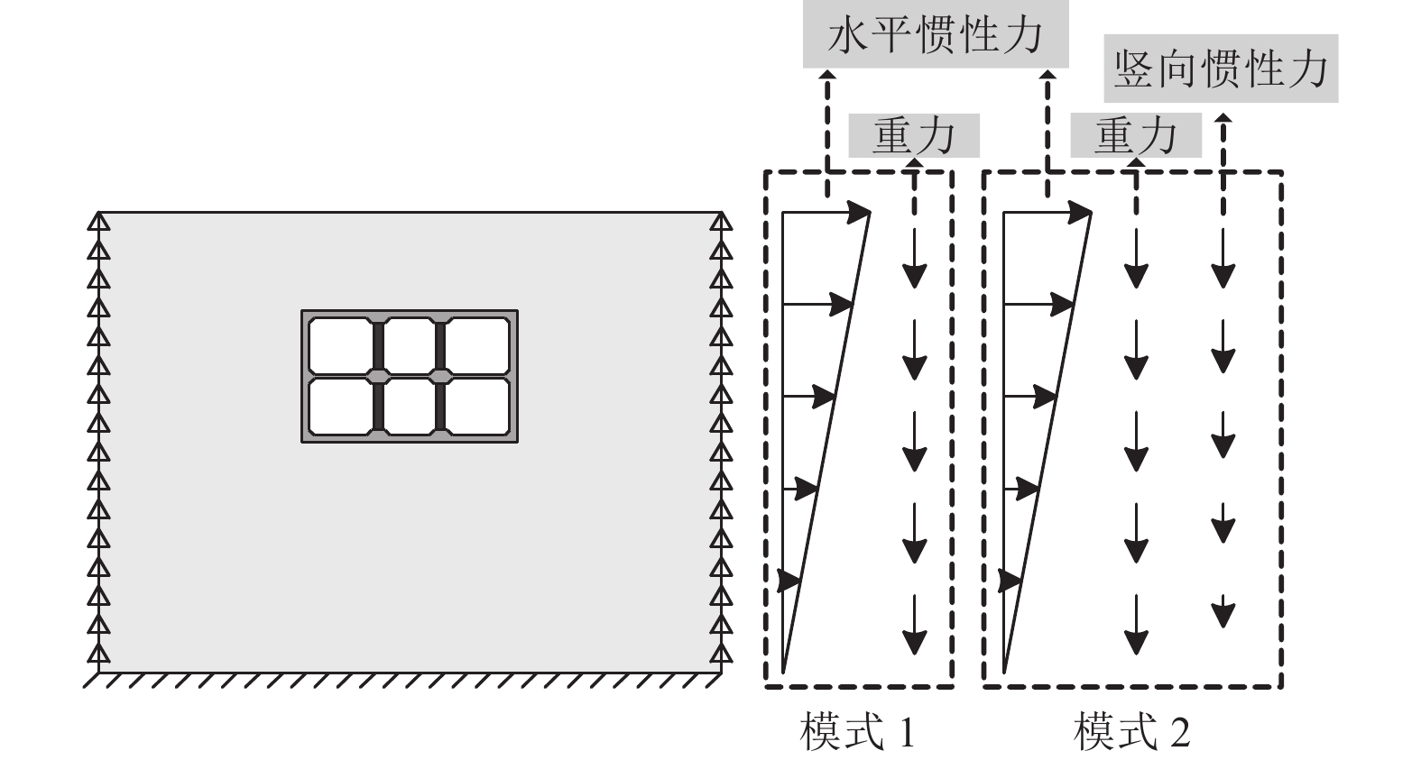
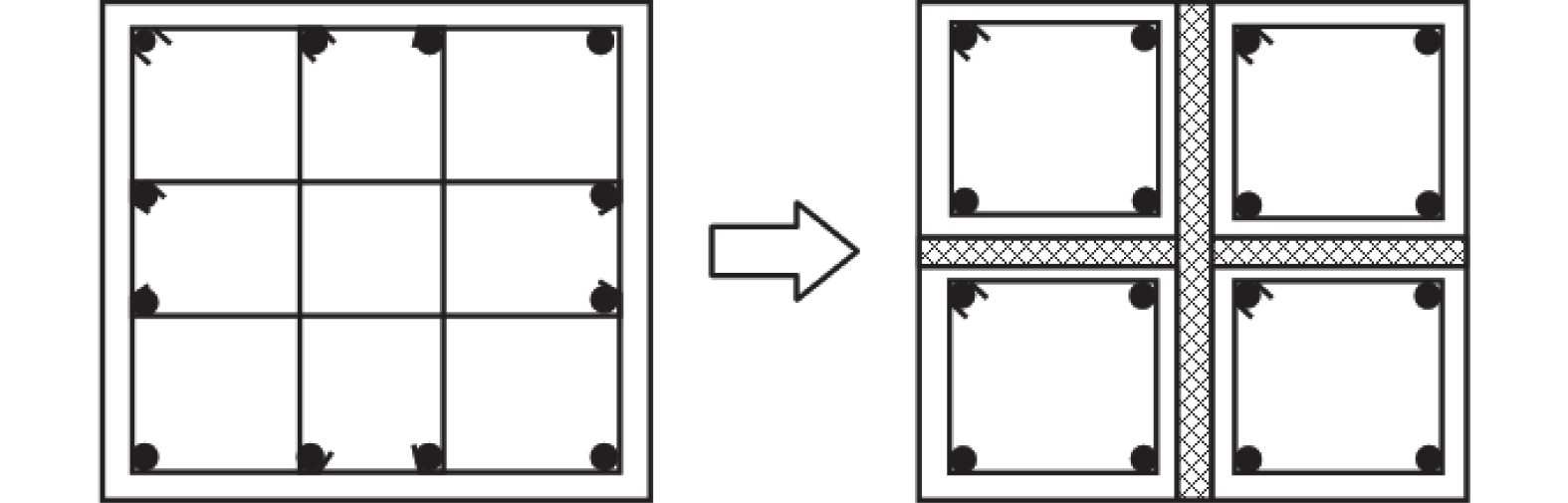
摘要: 浅埋地下车站结构中柱和地面高层结构底层中柱相似,地震作用下均需承担较大的竖向压力,易因变形能力不足发生脆性破坏。在某2层3跨地铁车站结构中引入地面高层结构中的分体柱设计理念,形成新型地下车站结构抗震体系。首先,通过拟静力推覆分析对比了传统钢筋混凝土中柱和分体柱在轴向压力作用下的水平变形特性;然后,建立了土-结构相互作用的拟静力推覆分析有限元模型,从关键截面内力、关键构件变形能力、关键构件塑性损伤等角度对比了传统钢筋混凝土中柱和分体柱的地下结构抗震性能差异。研究结果表明,将分体柱应用于2层3跨地铁车站结构中可提高整体结构抗震性能,其工作机理是避免分体柱承担过大的剪力和弯矩,并充分发挥分体柱竖向支撑能力和水平变形能力。Abstract: The center columns of shallow buried underground subway station structures are similar to columns in 1st floor of high-rise structures in that both are subject to large vertical pressures under earthquake action and are prone to brittle failure with insufficient deformation capacity. In this paper, the design concept of split column, which is used in high-rise structures, is introduced into a two-layer and three-span subway station structure to form a new underground structural seismic system. Firstly, the horizontal deformation characteristics of ordinary reinforced concrete column and split column under high axial pressure are compared by the quasi-static pushover analysis. Secondly, a numerical model is established for the quasi-static pushover analysis of the soil-structure system to compare the differences in seismic performance between the prototype structure and the new structure from the perspectives of internal forces of critical sections, deformation capacity of critical members, and plastic damage of critical members. The analysis results show that the split columns applied in two-layer and three-span subway stations can improve the seismic performance of the structure, and the working mechanism is to avoid the split columns from taking excessive shear forces and bending moments while giving full play to the vertical support capacity and horizontal deformation capacity of the split columns.
-
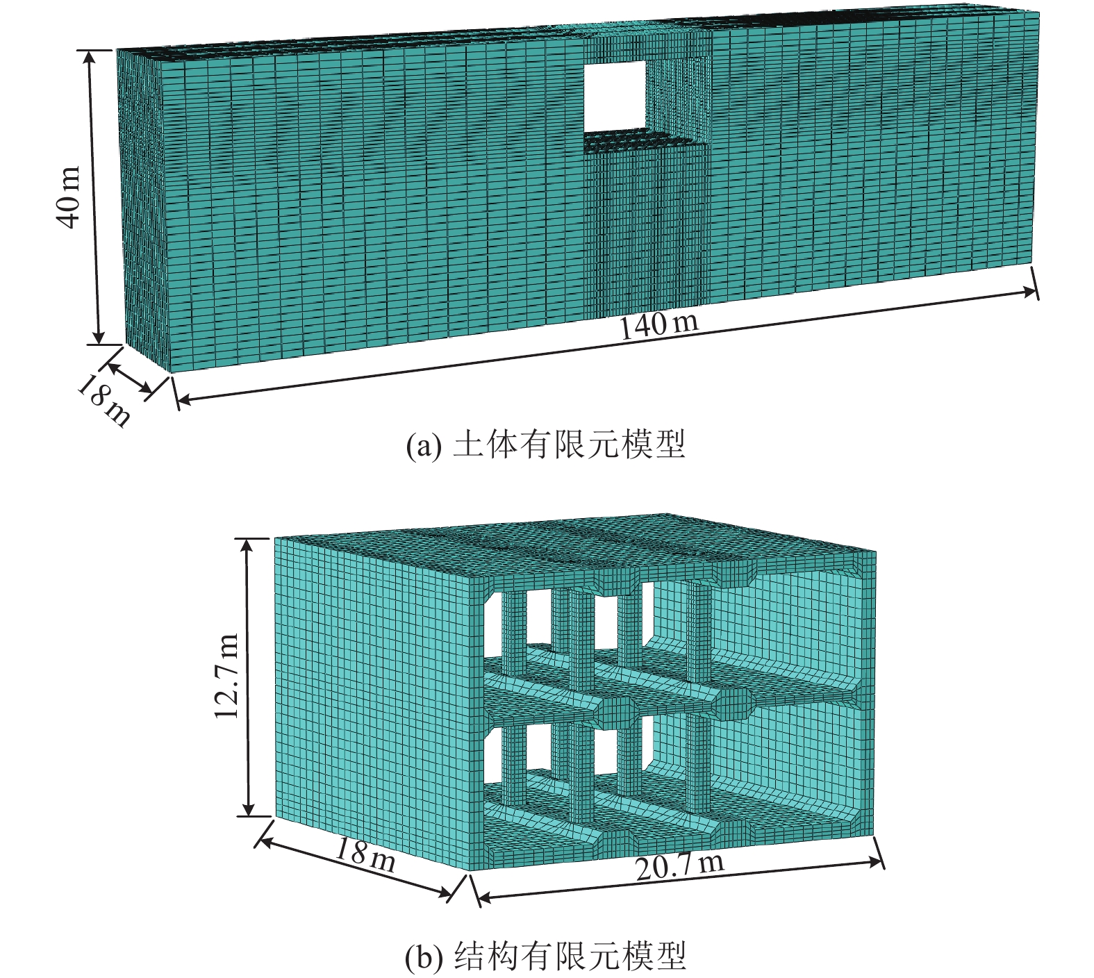
图 5 土-结构体系推覆分析有限元模型
Figure 5. Finite element model for pushover analysis of soil-structure system
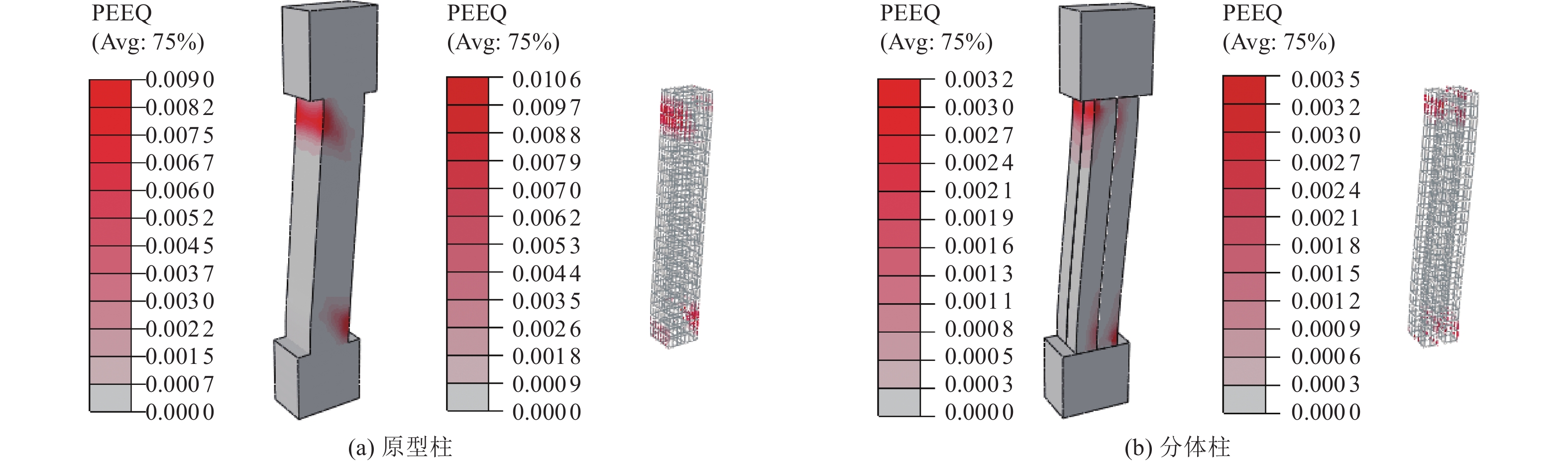
图 10 整体失效状态下中柱等效塑性应变
Figure 10. Equivalent plastic strain of central column at failure state
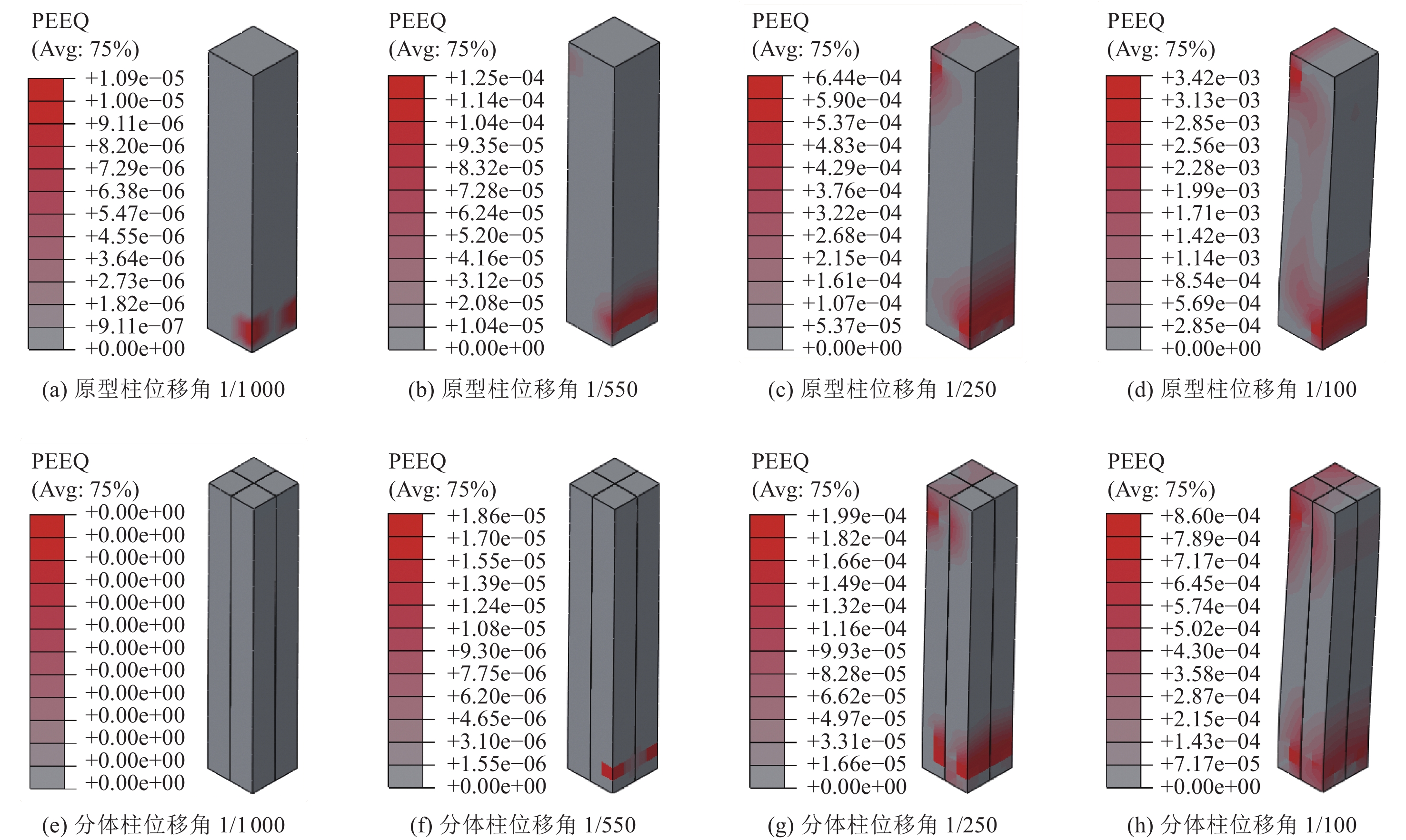
图 14 中柱混凝土等效塑性应变发展
Figure 14. Development of equivalent plastic strain of central column
表 1 土体材料参数
Table 1. Material parameters of soils
土层 深度/m 重度/(kN·m−3) 剪切波速/(m·s−1) 泊松比 A B γ0 土层① 0~4 19.0 200 0.3 1.02 0.35 4.0 土层② 4~8 19.5 260 0.3 1.05 0.34 3.5 土层③ 8~12 19.8 310 0.3 1.10 0.35 3.8 土层④ 12~20 19.5 335 0.3 1.10 0.35 3.8 土层⑤ 20~30 20.0 430 0.3 1.10 0.35 3.8 土层⑥ 30~40 21.0 520 0.3 1.20 0.35 2.5  下载: 导出CSV
-
陈国兴, 陈苏, 杜修力等, 2016. 城市地下结构抗震研究进展. 防灾减灾工程学报, 36(1): 1—23 doi: 10.13409/j.cnki.jdpme.2016.01.001Chen G. X. , Chen S. , Du X. L. , et al. , 2016. Review of seismic damage, model test, available design and analysis methods of urban underground structures: retrospect and prospect. Journal of Disaster Prevention and Mitigation Engineering, 36(1): 1—23. (in Chinese) doi: 10.13409/j.cnki.jdpme.2016.01.001 杜修力, 马超, 路德春等, 2017. 大开地铁车站地震破坏模拟与机理分析. 土木工程学报, 50(1): 53—62, 69 doi: 10.15951/j.tmgcxb.2017.01.007Du X. L. , Ma C. , Lu D. C. , et al. , 2017. Collapse simulation and failure mechanism analysis of the Daikai subway station under seismic loads. China Civil Engineering Journal, 50(1): 53—62, 69. (in Chinese) doi: 10.15951/j.tmgcxb.2017.01.007 杜修力, 王子理, 刘洪涛, 2018 a. 基于韧性设计的一种地下框架结构抗震新体系研究. 震灾防御技术, 13(3): 493—501Du X L. , Wang Z. L. , Liu H. T. , 2018 a. Study of a seismic new system of underground frame structure based on toughness design. Technology for Earthquake Disaster Prevention, 13(3): 493—501. (in Chinese) 杜修力, 许紫刚, 许成顺等, 2018 b. 浅埋地下结构地震反应分析的惯性力-位移法. 岩土工程学报, 40(4): 583—591Du X. L. , Xu Z. G. , Xu C. S. , et al. , 2018 b. Inertia force-displacement method for seismic analysis of shallow buried underground structures. Chinese Journal of Geotechnical Engineering, 40(4): 583—591. (in Chinese) 杜修力, 许紫刚, 许成顺等, 2019 a. 摩擦摆支座在地下地铁车站结构中的减震效果研究. 工程力学, 36(9): 60—67, 88Du X. L. , Xu Z. G. , Xu C. S. , et al. , 2019 a. Seismic mitigation effect analysis on friction pendulum bearing applied in the underground subway station. Engineering Mechanics, 36(9): 60—67, 88. (in Chinese) 杜修力, 蒋家卫, 许紫刚等, 2019 b. 浅埋矩形框架地铁车站结构抗震性能指标标定研究. 土木工程学报, 52(10): 111—119, 128 doi: 10.15951/j.tmgcxb.2019.10.009Du X. L. , Jiang J. W. , Xu Z. G. , et al. , 2019 b. Study on quantification of seismic performance index for rectangular frame subway station structure. China Civil Engineering Journal, 52(10): 111—119, 128. (in Chinese) doi: 10.15951/j.tmgcxb.2019.10.009 高峰, 石玉成, 严松宏等, 2005. 隧道的两种减震措施研究. 岩石力学与工程学报, 24(2): 222—229 doi: 10.3321/j.issn:1000-6915.2005.02.007Gao F. , Shi Y. C. , Yan S. H. , et al. , 2005. Study of two shock absorption measures in tunnel. Chinese Journal of Rock Mechanics and Engineering, 24(2): 222—229. (in Chinese) doi: 10.3321/j.issn:1000-6915.2005.02.007 韩润波, 许成顺, 许紫刚等, 2021. 对称地下结构抗震分析的边界强制反应位移法. 工程力学, 38(5): 50—60 doi: 10.6052/j.issn.1000-4750.2020.02.0075Han R. B. , Xu C. S. , Xu Z. G. , et al. , 2021. A boundary forced response displacement method for seismic analysis of symmetrical underground structures. Engineering Mechanics, 38(5): 50—60. (in Chinese) doi: 10.6052/j.issn.1000-4750.2020.02.0075 郝永昶, 胡庆昌, 徐云扉等, 1999. 低周反复水平荷载作用下分体柱承载力的试验研究. 建筑结构学报, 20(6): 18—25 doi: 10.14006/j.jzjgxb.1999.06.003Hao Y. C. , Hu Q. C. , Xu Y. F. , et al. , 1999. Experimental study on bearing capacity of separated columns under horizontal cyclic loading. Journal of Building Structures, 20(6): 18—25. (in Chinese) doi: 10.14006/j.jzjgxb.1999.06.003 李瑞伟, 2017. 不同分隔比的分体柱受力性能试验研究. 烟台: 烟台大学.Li R. W., 2017. Experimental study on the mechanical behavior of split columns with different separation ratios. Yantai: Yantai University. (in Chinese) 李忠献, 郝永昶, 张建宇等, 2001. 钢筋混凝土分体柱框架梁柱中节点抗震性能的研究. 建筑结构学报, 22(4): 55—60 doi: 10.3321/j.issn:1000-6869.2001.04.010Li Z. X. , Hao Y. C. , Zhang J. Y. , et al. , 2001. Research on seismic behavior of interior beam-column joints of reinforced concrete frames with split columns. Journal of Building Structures, 22(4): 55—60. (in Chinese) doi: 10.3321/j.issn:1000-6869.2001.04.010 李忠献, 郝永昶, 周兵等, 2003. 钢筋混凝土分体柱框架抗震性能的模型试验研究. 建筑结构学报, 24(6): 1—10, 31 doi: 10.3321/j.issn:1000-6869.2003.06.001Li Z. X. , Hao Y. C. , Zhou B. , et al. , 2003. Model experimental study on seismic behavior of reinforced concrete frame with split columns. Journal of Building Structures, 24(6): 1—10, 31. (in Chinese) doi: 10.3321/j.issn:1000-6869.2003.06.001 李忠献, 2005. 钢筋混凝土分体柱理论与技术. 工程力学, 22(S1): 127—141Li Z. X. , 2005. Theory and technology of split reinforced concrete columns. Engineering Mechanics, 22(S1): 127—141. (in Chinese) 马乾瑛, 赵广旗, 姜存玉, 2021. 地铁车站中柱抗震性能试验研究. 建筑结构, 51(4): 77—85Ma Q. Y. , Zhao G. Q. , Jiang C. Y. , 2021. Experimental research on seismic performance of central column in metro station. Building Structure, 51(4): 77—85. (in Chinese) 许成顺, 汪洋筱珊, 杜修力等, 2021. 分体柱在地下车站结构中的减震效果研究. 岩土工程学报, 43(4): 624—633Xu C. S. , Wang Y. X. S. , Du X. L. , et al. , 2021. Seismic mitigation effects of split columns in underground station structures. Chinese Journal of Geotechnical Engineering, 43(4): 624—633. (in Chinese) 钟紫蓝, 史跃波, 李锦强等, 2022. 考虑损伤界限模糊性的地铁车站结构抗震性能评价. 岩土工程学报, 44(12): 2196—2205Zhong Z. L. , Shi Y. B. , Li J. Q. , et al. , 2022. Seismic performance assessment of subway station structures considering fuzzy probability of damage states. Chinese Journal of Geotechnical Engineering, 44(12): 2196—2205. (in Chinese) 庄海洋, 2006. 土-地下结构非线性动力相互作用及其大型振动台试验研究. 南京: 南京工业大学.Zhuang H. Y., 2006. Study on nonlinear dynamic soil-underground structure interaction and its large-size shaking table test. Nanjing: Nanjing Tech University. (in Chinese) Chen Z. Y. , Chen W. , Bian G. Q. , 2014. Seismic performance upgrading for underground structures by introducing shear panel dampers. Advances in Structural Engineering, 17(9): 1343—1357. doi: 10.1260/1369-4332.17.9.1343 Chen Z. Y. , Zhan H. , Lou M. L. , 2016. Seismic performance and optimal design of framed underground structures with lead-rubber bearings. Structural Engineering and Mechanics, 58(2): 259—276. doi: 10.12989/sem.2016.58.2.259 Chen Z. Y. , Liang S. B. , Shen H. , et al. , 2018. Dynamic centrifuge tests on effects of isolation layer and cross-section dimensions on shield tunnels. Soil Dynamics and Earthquake Engineering, 109: 173—187. doi: 10.1016/j.soildyn.2018.03.002 Chen Z. Y. , Zhou Y. , 2019. Seismic performance of framed underground structures with self-centering energy-dissipation column base. Advances in Structural Engineering, 22(13): 2809—2822. doi: 10.1177/1369433219852043 Jiang J. W. , Xu C. S. , El Naggar H. M. , et al. , 2021. Improved pushover method for seismic analysis of shallow buried underground rectangular frame structure. Soil Dynamics and Earthquake Engineering, 140: 106363. doi: 10.1016/j.soildyn.2020.106363 Lee J. , Fenves G. L. , 1998. Plastic-damage model for cyclic loading of concrete structures. Journal of Engineering Mechanics, 124(8): 892—900. doi: 10.1061/(ASCE)0733-9399(1998)124:8(892) Liu J. B. , Wang W. H. , Dasgupta G. , 2014. Pushover analysis of underground structures: method and application. Science China Technological Sciences, 57(2): 423—437. doi: 10.1007/s11431-013-5430-z Ma C. , Lu D. C. , Du X. L. , 2018. Seismic performance upgrading for underground structures by introducing sliding isolation bearings. Tunnelling and Underground Space Technology, 74: 1—9. doi: 10.1016/j.tust.2018.01.007 Zhao W. S. , Chen W. Z. , Yang D. S. , 2018. Interaction between strengthening and isolation layers for tunnels in rock subjected to SH waves. Tunnelling and Underground Space Technology, 79: 121—133. doi: 10.1016/j.tust.2018.05.012 Zhuang H. Y. , Hu Z. H. , Wang X. J. , et al. , 2015. Seismic responses of a large underground structure in liquefied soils by FEM numerical modelling. Bulletin of Earthquake Engineering, 13(12): 3645—3668. doi: 10.1007/s10518-015-9790-6 -


 点击查看大图
计量
- 文章访问数: 357
- HTML全文浏览量: 49
- PDF下载量: 51
- 被引次数: 0
