
Discuss on Plain Strain Model for Seismic Response of Underground Structure
-
摘要: 采用平面应变模型对地下结构进行地震反应分析时,其核心问题是中柱的二维等效简化。常用的简化方法是将中柱的材料性质(如弹性模量和密度)进行折减。在此基础上,进一步引入空间约束影响系数和三维还原系数,提出新的中柱二维等效简化方法。针对不同简化方法,分别建立对应的地下结构地震反应分析平面应变模型,计算各模型的地震反应。通过与三维模型计算结果进行对比分析,研究不同简化方法的合理性。计算结果表明,本研究建议的方法可有效提高地下结构平面应变模型的计算精度。Abstract: The method to simplify inner column is a key point when plane strain model is picked to compute seismic response of underground structure. The commonly used simplification method for the inner columns is to reduce its values of material properties, such as Young’s Modulus and density. Based on common methods, the space constraint influence coefficient and the three-dimensional reduction coefficient were introduced in this paper furtherly, and a new plane strain model simplified method for the center column was proposed. According to three different simplified methods, three plane strain models for seismic response analysis of underground structures were established respectively, and the seismic response of each model was calculated. By comparing the calculation results with the three-dimensional model, the rationality of different simplification methods was discussed. The calculation results show that the method proposed in this paper can effectively improve the calculation accuracy of the plane strain model of underground structures.
-
Key words:
- Underground structure /
- Seismic response /
- Plain strain model /
- Error of internal force
-
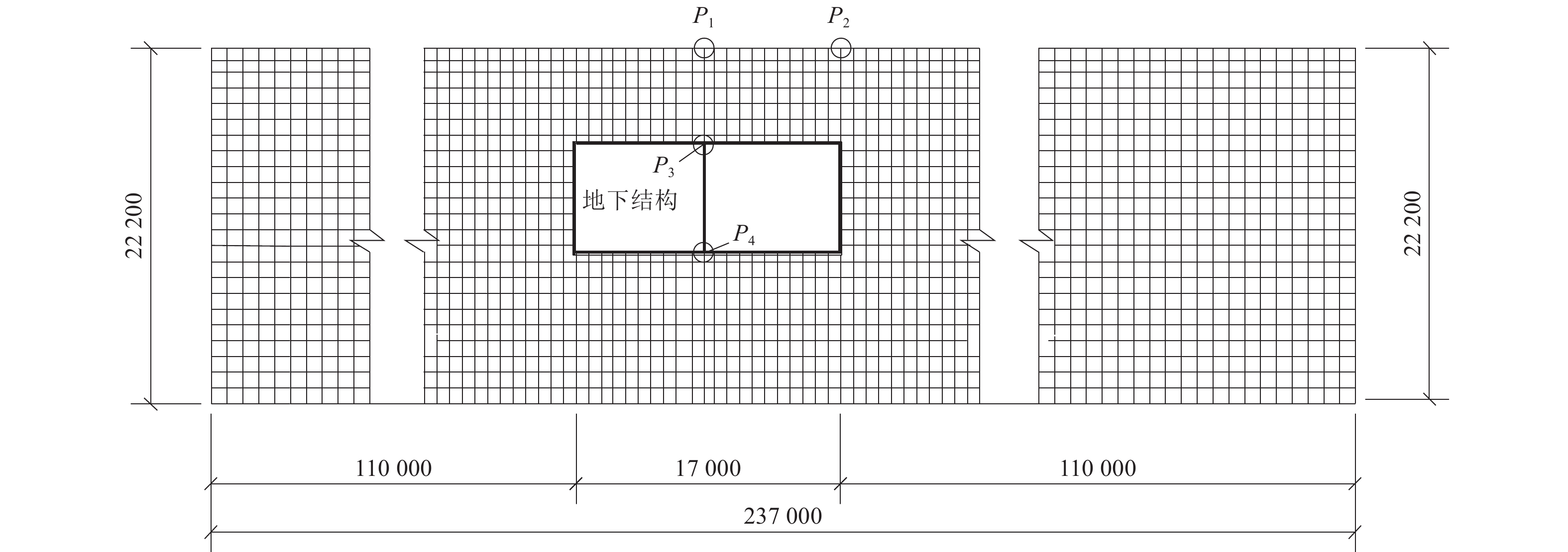
图 2 有限元网格示意与监测点位置(单位:毫米)
Figure 2. The mesh of finite element and observation points(Unit: mm)
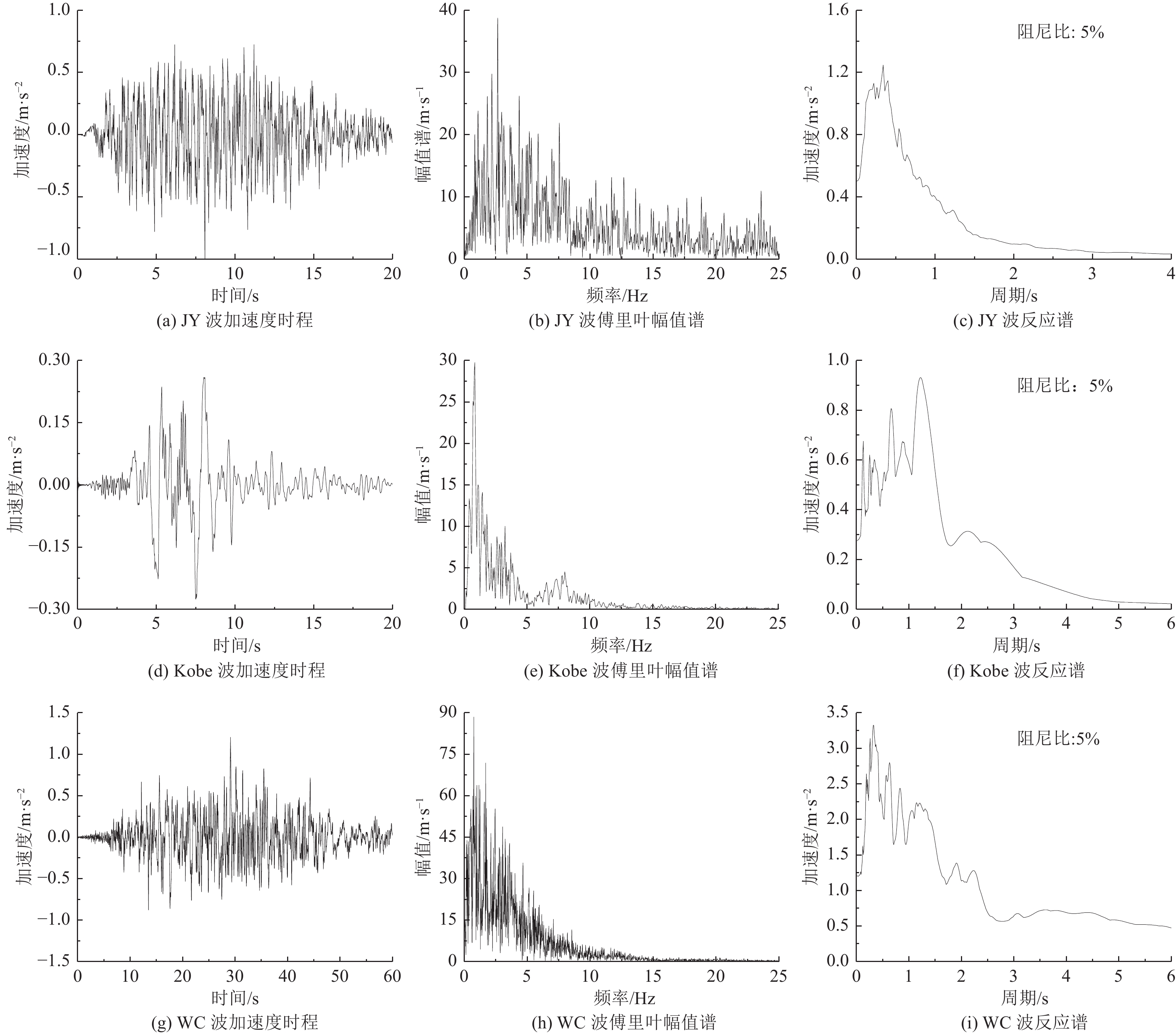
图 3 地震波加速度时程、傅里叶幅值谱和反应谱
Figure 3. Time history of exciting and its Fourier spectrum and its response spectrum
表 1 场地土物理力学参数
Table 1. Physical parameters of site soil properties
土质 深度/m 密度/t·m−3 剪切波速/m·s−1 最大剪切模量/MPa 泊松比 人工填土 0~1.0 1.9 140 38.00 0.33 全新世砂土 1.0~5.1 1.9 140 38.00 0.32 全新世砂土 5.1~8.3 1.9 170 56.03 0.32 更新世黏土 8.3~11.4 1.9 190 69.99 0.40 更新世黏土 11.4~17.2 1.9 240 111.67 0.30 更新世砂土 17.2~22.2 2.0 330 222.24 0.26  下载: 导出CSV
表 2 三维模型的前7阶自振频率及横向(水平向)振型参与系数
Table 2. The first seven natural frequencies of three dimension model and modal participation factor of horizontal direction
参数 阶序 1 2 3 4 5 6 7 自振频率/Hz 2.66 2.72 2.73 2.76 2.77 2.79 2.89 参与系数/×104 1.00 0 0 0 0 0 0.48
下载: 导出CSV
表 3 二维模型的前7阶自振频率及横向(水平向)振型参与系数
Table 3. The first seven natural frequencies of two dimension model and modal participation factor of horizontal direction
参数 阶序 1 2 3 4 5 6 7 自振频率/Hz 2.64 2.79 2.87 3.24 3.45 3.95 4.20 参与系数/×104 0.23 0 0.10 0 0.25 0 0.02
下载: 导出CSV
表 4 中柱地震反应峰值
Table 4. Peak seismic response of the inner column
激励 考察点及反应量 三维模型 方法1 方法1a 方法2 方法2a 方法3 JY波 柱顶
(监测点P2)弯矩Mz/kN·m 253.61 84.12
(误差−66.83%)294.42
(误差16.09%)92.21
(误差−63.64%)322.72
(误差27.25%)263.87
(误差4.04%)剪力Fx/kN 60.40 13.71
(误差−77.29%)48.00
(误差−20.52%)22.54
(误差−62.68%)78.89
(误差30.63%)64.60
(误差6.97%)柱底
(监测点P3)弯矩Mz/kN·m 246.16 95.92
(误差−61.03%)335.74
(误差36.39%)88.93
(误差−63.87%)311.26
(误差26.44%)254.02
(误差3.19%)剪力Fx/kN 77.62 33.22
(误差−57.20%)116.28
(误差49.81%)27.61
(误差−64.43%)96.62
(误差24.48%)78.74
(误差1.44%)Kobe波 柱顶
(监测点P2)弯矩Mz/kN·m 52.13 16.82
(误差−67.72%)58.89
(误差12.97%)18.51
(误差−64.49%)64.78
(误差24.27%)52.90
(误差1.48%)剪力Fx/kN 12.57 2.90
(误差−76.94%)10.15
(误差−19.29%)4.55
(误差−63.80%)15.93
(误差26.71%)13.03
(误差3.62%)柱底
(监测点P3)弯矩Mz/kN·m 51.07 19.46
(误差−61.89%)68.12
(误差33.38%)18.02
(误差−64.72%)63.07
(误差23.50%)51.40
(误差0.65%)剪力Fx/kN 16.08 6.60
(误差−58.95%)23.10
(误差43.69%)5.61
(误差−65.09%)19.64
(误差22.17%)16.00
(误差−0.46%)WC波 柱顶
(监测点P2)弯矩Mz/kN·m 307.13 96.51
(误差−68.58%)337.79
(误差9.98%)105.99
(误差−65.49%)370.98
(误差20.79%)303.11
(误差−1.31%)剪力Fx/kN 73.78 16.79
(误差−77.24%)58.78
(误差−20.33%)26.11
(误差−64.62%)91.37
(误差23.84%)74.76
(误差1.34%)柱底
(监测点P3)弯矩Mz/kN·m 304.37 112.25
(误差−63.12%)392.87
(误差29.08%)103.49
(误差−66.00%)362.23
(误差19.01%)295.34
(误差−2.96%)剪力Fx/kN 96.71 38.91
(误差−59.77%)136.17
(误差40.80%)32.45
(误差−66.45%)113.56
(误差17.42%)92.43
(误差−4.43%)
下载: 导出CSV
表 5 关键点地震反应峰值
Table 5. Peak seismic response of observation points
激励 考察点
及反应量三维模型 方法1 方法2 方法3 JY波 地表
(监测点P1)加速度a/m·s−2 4.22 4.49(误差6.32%) 4.48(误差6.21%) 4.49(误差6.32%) 位移u/mm 14.53 15.58(误差7.21%) 15.47(误差6.43%) 15.50(误差6.69%) 柱顶
(监测点P2)加速度a/m·s−2 4.53 4.99(误差10.22%) 4.96(误差9.49%) 4.98(误差9.81%) 位移u/mm 13.69 15.38(误差12.29%) 15.23(误差11.23%) 15.30(误差11.7%) 侧壁
(监测点P4)加速度a/m·s−2 1.64 1.62(误差−1.10%) 1.61(误差−2.13%) 1.61(误差−2.25%) 位移u/mm 3.41 3.48(误差1.85%) 3.46(误差1.28%) 3.45(误差1.02%) Kobe波 地表
(监测点P1)加速度a/m·s−2 0.86 0.87(误差1.20%) 0.87(误差1.01%) 0.87(误差1.00%) 位移u/mm 3.10 3.18(误差2.41%) 3.16(误差1.96%) 3.17(误差2.07%) 柱顶
(监测点P2)加速度a/m·s−2 0.80 0.85(误差6.06%) 0.84(误差5.51%) 0.84(误差5.82%) 位移u/mm 2.94 3.10(误差5.45%) 3.08(误差4.80%) 3.09(误差5.14%) 侧壁
(监测点P4)加速度a/m·s−2 0.30 0.29(误差−2.89%) 0.29(误差−3.72%) 0.29(误差−3.96%) 位移u/mm 0.78 0.77(误差−1.11%) 0.77(误差−1.50%) 0.77(误差−1.76%) WC波 地表
(监测点P1)加速度a/m·s−2 5.13 5.18(误差0.82%) 5.17(误差0.69%) 5.17(误差0.63%) 位移u/mm 18.75 18.62(误差−0.72%) 18.55(误差−1.10%) 18.56(误差−1.03%) 柱顶
(监测点P2)加速度a/m·s−2 4.80 4.87(误差1.54%) 4.86(误差1.27%) 4.87(误差1.44%) 位移u/mm 17.81 18.33(误差2.94%) 18.23(误差2.36%) 18.28(误差2.66%) 侧壁
(监测点P4)加速度a/m·s−2 1.39 1.40(误差1.12%) 1.39(误差0.62%) 1.39(误差0.47%) 位移u/mm 4.45 4.33(误差−2.66%) 4.32(误差−2.96%) 4.30(误差−3.26%)
下载: 导出CSV
-
曹炳政, 罗奇峰, 马硕等, 2002. 神户大开地铁车站的地震反应分析. 地震工程与工程振动, 22(4): 102—107 doi: 10.3969/j.issn.1000-1301.2002.04.017Cao B. Z. , Luo Q. F. , Ma S. , et al. , 2002. Seismic response analysis of Dakai subway station in Hyogoken-Nanbu earthquake. Earthquake Engineering and Engineering Vibration, 22(4): 102—107. (in Chinese) doi: 10.3969/j.issn.1000-1301.2002.04.017 陈国兴, 孙瑞瑞, 赵丁凤等, 2019. 海底盾构隧道纵向地震反应特征的子模型分析. 岩土工程学报, 41(11): 1983—1991Chen G. X. , Sun R. R. , Zhao D. F. , et al. , 2019. Longitudinal Seismic response characteristics of seabed shield tunnels using submodeling analysis. Chinese Journal of Geotechnical Engineering, 41(11): 1983—1991. (in Chinese) 杜修力, 马超, 路德春等, 2017. 大开地铁车站地震破坏模拟与机理分析. 土木工程学报, 50(1): 53—62, 69 doi: 10.15951/j.tmgcxb.2017.01.007Du X. L. , Ma C. , Lu D. C. , et al. , 2017. Collapse simulation and failure mechanism analysis of the Daikai subway station under seismic loads. China Civil Engineering Journal, 50(1): 53—62, 69. (in Chinese) doi: 10.15951/j.tmgcxb.2017.01.007 杜修力, 康凯丽, 许紫刚等, 2018. 地下结构地震反应的主要特征及规律. 土木工程学报, 51(7): 11—21 doi: 10.15951/j.tmgcxb.2018.07.002Du X. L. , Kang K. L. , Xu Z. G. , et al. , 2018. Main characteristics and rules of seismic response for underground structures. China Civil Engineering Journal, 51(7): 11—21. (in Chinese) doi: 10.15951/j.tmgcxb.2018.07.002 韩文星, 2005. 软土地铁车站结构横向抗震设计方法研究. 上海: 同济大学. 刘晶波, 李彬, 2006. 地铁地下结构抗震分析及设计中的几个关键问题. 土木工程学报, 39(6): 106—110 doi: 10.3321/j.issn:1000-131X.2006.06.019Liu J. B. , Li B. , 2006. Issues on the seismic analysis and design of subway structures. China Civil Engineering Journal, 39(6): 106—110. (in Chinese) doi: 10.3321/j.issn:1000-131X.2006.06.019 楼梦麟, 董云, 张如林, 2016. 沉管隧道地震反应分析局部精细化建模中的几个问题. 岩土工程学报, 38(9): 1705—1712 doi: 10.11779/CJGE201609018Lou M. L. , Dong Y. , Zhang R. L. , 2016. Several problems in refined local modeling for seismic response analysis of immersed tunnel. Chinese Journal of Geotechnical Engineering, 38(9): 1705—1712. (in Chinese) doi: 10.11779/CJGE201609018 舒恩, 2020. 增强地下结构中柱抗震能力的方法研究. 淮南: 安徽理工大学.Shu E., 2020. Study on the method of strengthening the seismic capacity of the middle column of underground structure. Huainan: Anhui University of Technology. (in Chinese) 田雪娟, 2010. 地铁车站抗震分析. 北京: 北京交通大学.Tian X. J., 2010. Seismic analysis of subway station. Beijing: Beijing Jiaotong University. (in Chinese) 王国波, 王亚西, 陈斌等, 2015. 隧道–土体–地表结构相互作用体系地震响应影响因素分析. 岩土力学与工程学报, 34(6): 1276—1287Wang G. B. , Wang Y. X. , Chen B. , et al. , 2015. Analysis of factors influencing seismic responses of tunnel-soil-ground structural system. Chinese Journal of Rock Mechanics and Engineering, 34(6): 1276—1287. (in Chinese) 许紫刚, 杜修力, 许成顺等, 2019. 地下结构地震反应分析中场地瑞利阻尼构建方法比较研究. 岩土力学, 40(12): 4838—4847 doi: 10.16285/j.rsm.2018.1913Xu Z. G. , Du X. L. , Xu C. S. , et al. , 2019. Comparison of determination methods of site Rayleigh damping coefficients in seismic responses analysis of underground structures. Rock and Soil Mechanics, 40(12): 4838—4847. (in Chinese) doi: 10.16285/j.rsm.2018.1913 庄海洋, 王修信, 陈国兴, 2009. 软土层埋深变化对地铁车站结构地震反应的影响规律研究. 岩土工程学报, 31(8): 1258—1266 doi: 10.3321/j.issn:1000-4548.2009.08.017Zhuang H. Y. , Wang X. X. , Chen G. X. , 2009. Earthquake responses of subway station with different depths of soft soil. Chinese Journal of Geotechnical Engineering, 31(8): 1258—1266. (in Chinese) doi: 10.3321/j.issn:1000-4548.2009.08.017 庄海洋, 任佳伟, 王瑞等, 2019. 两层三跨框架式地铁地下车站结构弹塑性工作状态与抗震性能水平研究. 岩土工程学报, 41(1): 131—138Zhuang H. Y. , Ren J. W. , Wang R. , et al. , 2019. Elasto-plastic working states and seismic performance levels of frame-type subway underground station with two layers and three spans. Chinese Journal of Geotechnical Engineering, 41(1): 131—138. (in Chinese) Hashash Y. M. A. , Hook J. J. , Schmidt B. , et al. , 2001. Seismic design and analysis of underground structures. Tunnelling and Underground Space Technology, 16(4): 247—293. doi: 10.1016/S0886-7798(01)00051-7 -

 点击查看大图

计量
- 文章访问数: 204
- HTML全文浏览量: 209
- PDF下载量: 38
- 被引次数: 0
