Accurate Mesh Generation of Undulating Interface Based on Truegrid and the Ground Motion Simulation
-
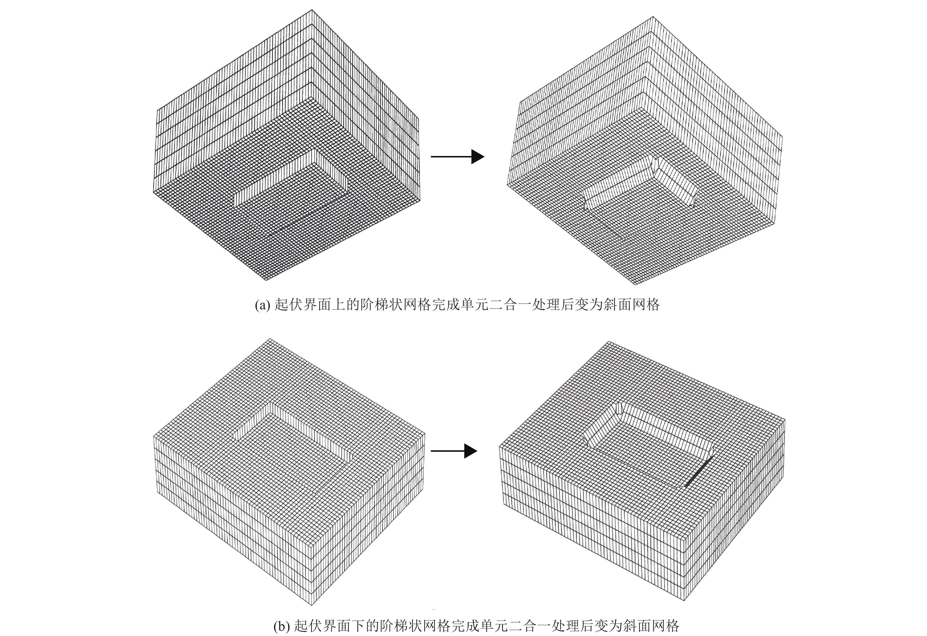
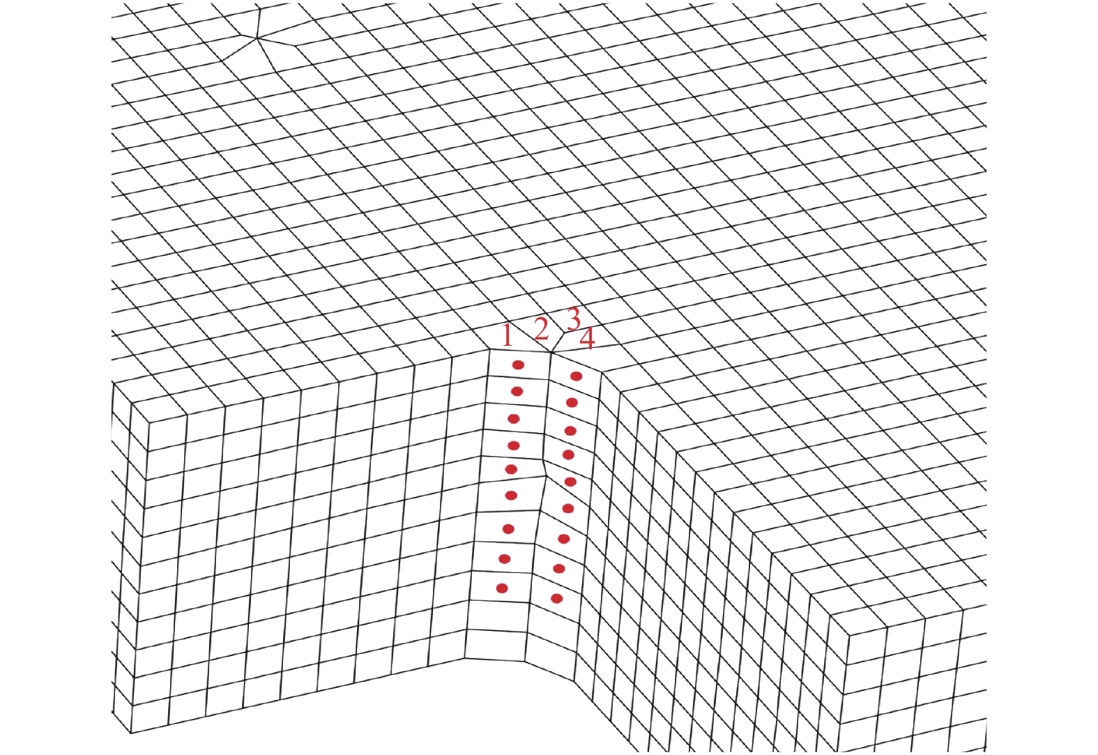
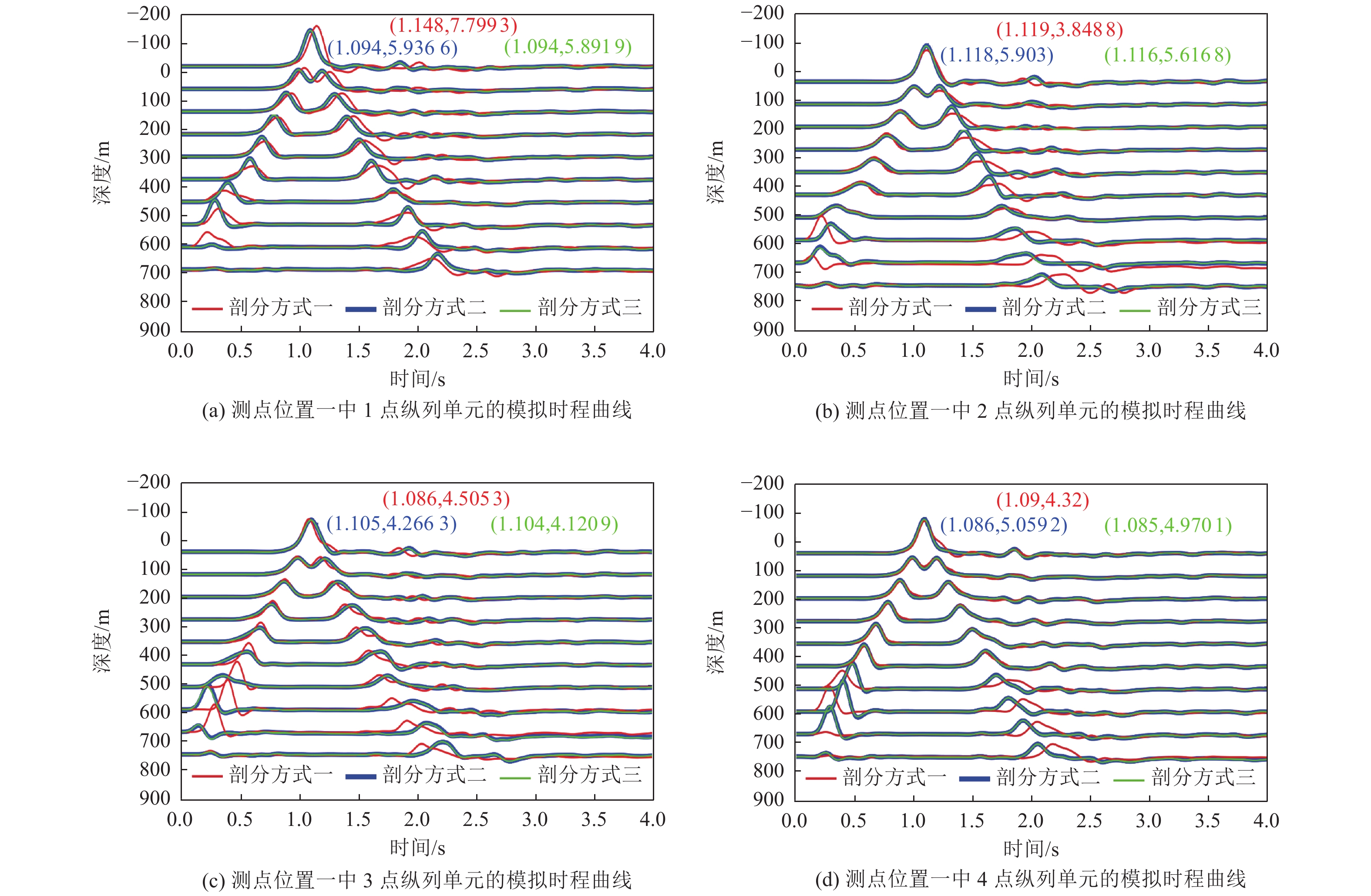
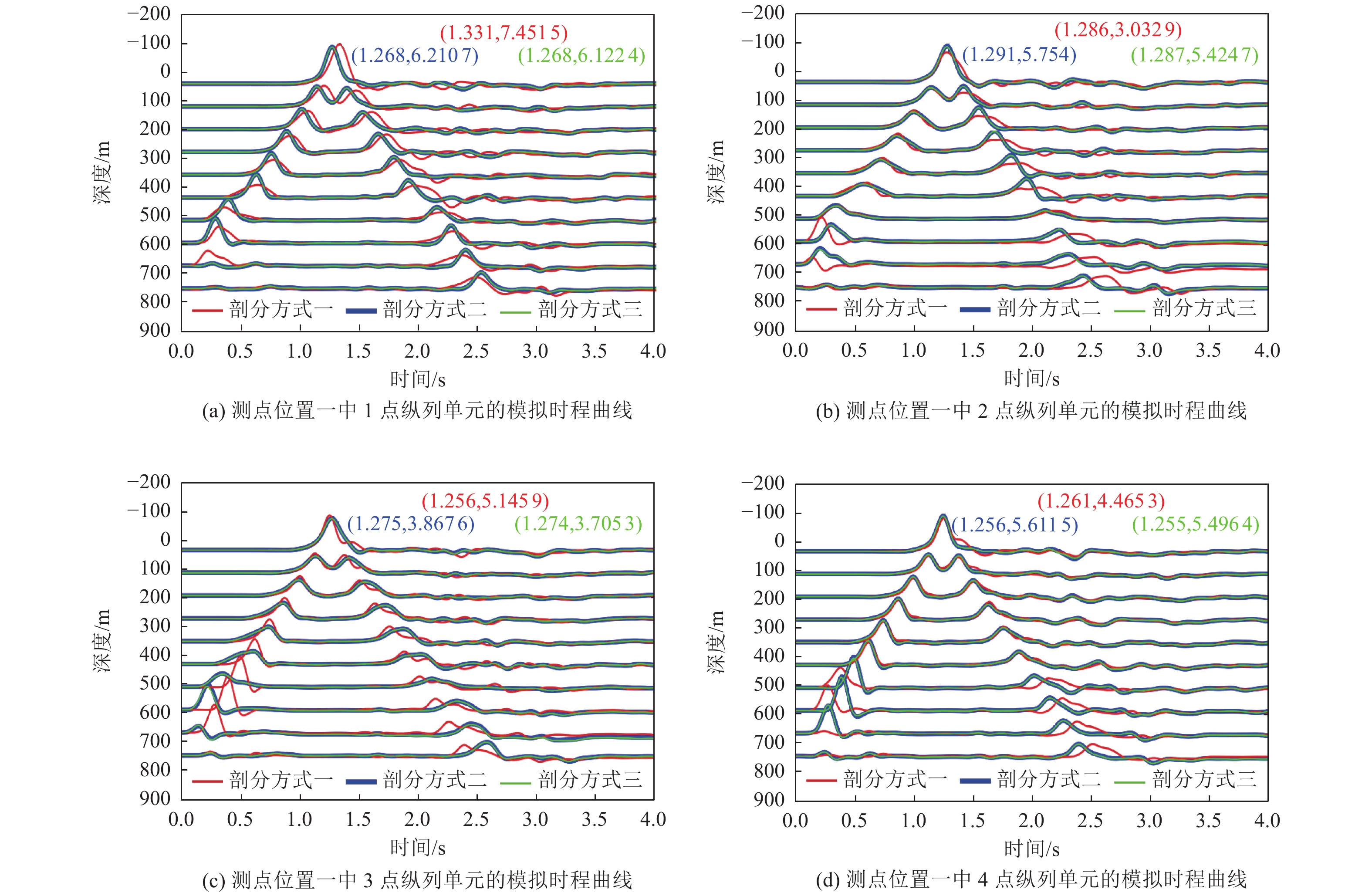
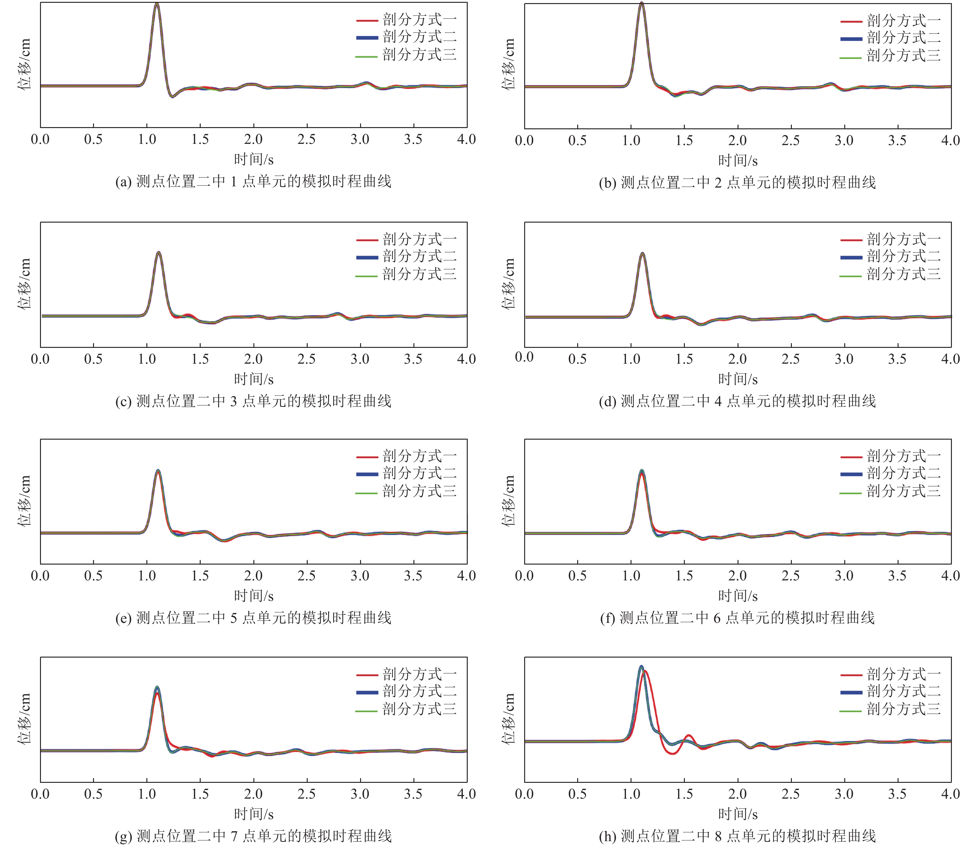
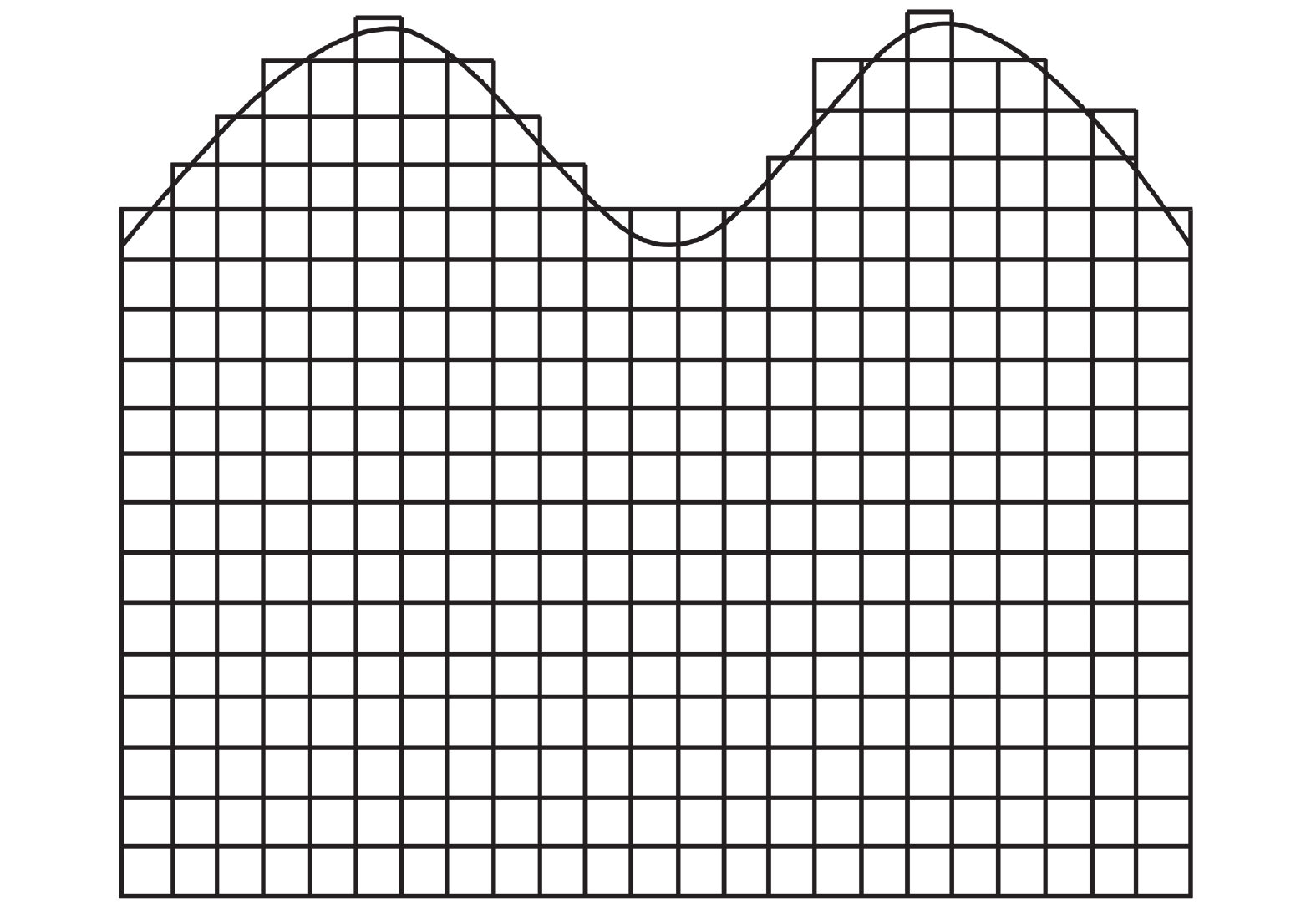
摘要: 利用谱元法的规则六面体单元进行网格剖分时,界面起伏较大处会出现阶梯状网格而导致模拟时产生数值散射。为消除阶梯状网格对起伏界面地震动模拟计算的影响,本文基于TrueGrid软件编写了应用程序,提出了起伏界面处六面体单元网格剖分方式,通过该程序可快速建立起伏界面处均匀的六面体网格模型。本文采取了删除四纵列拐角单元、删除一纵列拐角单元以及构造单元过渡环3种剖分方式,解决两个方向上(x-z与y-z方向)单元二合一过渡后拐角处产生扭曲单元的问题。将阶梯状网格经二合一处理后变为斜面网格,并投影至起伏界面,使得网格完全贴合起伏界面,改善了用台阶状网格近似描绘起伏界面的问题。将3种模型通过谱元法进行数值模拟计算验证了该剖分方式的正确性,对比结果发现删除拐角处一纵列单元方式与设置过渡环的方式均可使用,删除四纵列拐角单元方式不推荐使用,本文提出的方案有助于提高谱元法处理起伏界面问题的灵活性。Abstract: When the regular hexahedral element of the spectral element method is used for meshing, a stepped grid will appear where the interface fluctuates greatly, which leads to numerical scattering during simulation. In order to eliminate the influence of the stepped grid on the ground motion simulation calculation of the undulating interface, an application program is written based on the TrueGrid software, and a method of meshing hexahedral element at the undulating interface is proposed. By using this program, a uniform hexahedral mesh model at the undulating interface can be quickly established. This paper adopts three meshing methods: deleting four-column corner elements, deleting one-column corner elements, and constructing element transition rings to solve the problem of twisting elements at the corners after the two-in-one transition of the elements in the two directions (x-z and y-z directions). The stepped grid is transformed into an inclined grid after two-in-one processing, and projected to the undulating interface, so that the grid fits the undulating interface completely, and the problem of using a stepped grid to approximate the undulating interface is improved. Numerical simulations of the three models verify the correctness of the subdivision method. Comparing the results, it is found that both the method of deleting one column of elements at the corner and the method of setting a transition ring are effective,but the method of deleting four columns of corner elements is not recommended. The schemes proposed in this paper can help to improve the flexibility of the spectral element method to deal with undulating interface problems.
-
Key words:
- Mesh generation /
- Hexahedral element /
- Spectral element method /
- Numerical simulation
-
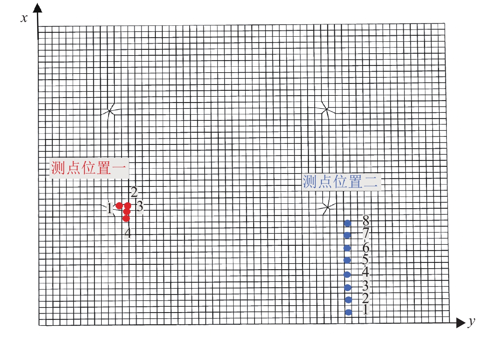
表 1 模型基本参数
Table 1. Basic parameters of the model
模型尺寸/m 总步长/步 格点间距/m 时间步长/s 震源时间函数主频/Hz 震源时间函数 6 000×5 000×1 100(长×宽×深) 4 000 100 0.001 4 主频为4 Hz的Ricker子波 -
[1] 董良国, 马在田, 曹景忠等, 2000. 一阶弹性波方程交错网格高阶差分解法. 地球物理学报, 43(3): 411—419 doi: 10.3321/j.issn:0001-5733.2000.03.015Dong L. G. , Ma Z. T. , Cao J. Z. , et al. , 2000. A staggered-grid high-order difference method of one-order elastic wave equation. Chinese Journal of Geophysics, 43(3): 411—419. (in Chinese) doi: 10.3321/j.issn:0001-5733.2000.03.015 [2] 董良国, 李培明, 2004. 地震波传播数值模拟中的频散问题. 天然气工业, 24(6): 53—56 doi: 10.3321/j.issn:1000-0976.2004.06.016Dong L. G. , Li P. M. , 2004. Dispersive problem in seismic wave propagation numerical modeling. Natural Gas Industry, 24(6): 53—56. (in Chinese) doi: 10.3321/j.issn:1000-0976.2004.06.016 [3] 付长华, 高孟潭, 陈鲲, 2012. 北京盆地结构对长周期地震动反应谱的影响. 地震学报, 34(3): 374—382 doi: 10.3969/j.issn.0253-3782.2012.03.009Fu C. H. , Gao M. T. , Chen K. , 2012. A study on long-period response spectrum of ground motion affected by basin structure of Beijing. Acta Seismologica Sinica, 34(3): 374—382. (in Chinese) doi: 10.3969/j.issn.0253-3782.2012.03.009 [4] 高孟潭, 俞言祥, 张晓梅等, 2002. 北京地区地震动的三维有限差分模拟. 中国地震, 18(4): 356—364 doi: 10.3969/j.issn.1001-4683.2002.04.005Gao M. T. , Yu Y. X. , Zhang X. M. , et al. , 2002. Three-dimensional finite-difference simulations of ground motions in the Beijing area. Earthquake Research in China, 18(4): 356—364. (in Chinese) doi: 10.3969/j.issn.1001-4683.2002.04.005 [5] 国家地震局, 1986. 中国地壳上地幔地球物理探测成果. 北京: 地震出版社. [6] 金安蜀, 刘福田, 孙永智, 1980. 北京地区地壳和上地幔的三维P波速度结构. 地球物理学报, 23(2): 172—182 doi: 10.3321/j.issn:0001-5733.1980.02.006Jin A. S. , Liu F. T. , Sun Y. Z. , 1980. Three-dimensional P velocity structure of the crust and upper mantle under Beijing region. Chinese Journal of Geophysics, 23(2): 172—182. (in Chinese) doi: 10.3321/j.issn:0001-5733.1980.02.006 [7] 罗宏伟, 郭鹏, 王树山等, 2013. 基于TrueGrid软件的射孔弹有限元仿真模型参数化建立方法. 测井技术, 37(2): 219—222 doi: 10.3969/j.issn.1004-1338.2013.02.022Luo H. W. , Guo P. , Wang S. S. , et al. , 2013. Parametric modeling method for finite element simulation of perforating charge based on TrueGrid software. Well Logging Technology, 37(2): 219—222. (in Chinese) doi: 10.3969/j.issn.1004-1338.2013.02.022 [8] 蒙茂洲, 2010. 功能强大的网格生成软件——TrueGrid. CAD/CAM与制造业信息化, (1): 57—60. [9] 孙建国, 2007. 复杂地表条件下地球物理场数值模拟方法评述. 世界地质, 26(3): 345—362 doi: 10.3969/j.issn.1004-5589.2007.03.015Sun J. G. , 2007. Methods for numerical modeling of geophysical fields under complex topographical conditions: a critical review. Global Geology, 26(3): 345—362. (in Chinese) doi: 10.3969/j.issn.1004-5589.2007.03.015 [10] 孙若昧, 赵燕来, 吴丹, 1996. 京津唐地区地壳结构与强震的发生──Ⅱ. S波速度结构. 地球物理学报, 39(3): 347—355Sun R. M. , Zhao Y. L. , Wu D. , 1996. Crust structures and strong earthquakes in the Beijing, Tianjin, Tangshan area: Ⅱ. S wave velocity structure. Acta Geophysica Sinica, 39(3): 347—355. (in Chinese) [11] 王夫运, 张先康, 陈棋福等, 2005. 北京地区上地壳三维细结构层析成像. 地球物理学报, 48(2): 359—366 doi: 10.3321/j.issn:0001-5733.2005.02.018Wang F. Y. , Zhang X. K. , Chen Q. F. , et al. , 2005. Fine tomographic inversion of the upper crust 3-D structure around Beijing. Chinese Journal of Geophysics, 48(2): 359—366. doi: 10.3321/j.issn:0001-5733.2005.02.018 [12] 王瑞, 高曙明, 吴海燕, 2020. 六面体网格生成和优化研究进展. 计算机辅助设计与图形学学报, 32(5): 693—708Wang R. , Gao S. M. , Wu H. Y. , 2020. Progress in hexahedral mesh generation and optimization. Journal of Computer-Aided Design & Computer Graphics, 32(5): 693—708. [13] 赵金仁, 张先康, 张成科等, 1999. 香河-北京-涿鹿及其相邻地区壳幔构造与速度结构特征. 地震地质, 21(1): 29—36 doi: 10.3969/j.issn.0253-4967.1999.01.004Zhao J. R. , Zhang X. K. , Zhang C. K. , et al. , 1999. The crust-mantle tectonics and velocity structure characteristics in Xianghe-Beijing-Zhulu and its adjacent areas. Seismology and Geology, 21(1): 29—36. doi: 10.3969/j.issn.0253-4967.1999.01.004 [14] Alford R. M. , Kelly K. R. , Boore D. M. , 1974. Accuracy of finite-difference modeling of the acoustic wave equation. Geophysics, 39(6): 834—842. doi: 10.1190/1.1440470 [15] Alterman Z. , Karal Jr F. C. , 1968. Propagation of elastic waves in layered media by finite difference methods. Bulletin of the Seismological Society of America, 58(1): 367—398. [16] Crase E. , Pica A. , Noble M. , et al. , 1990. Robust elastic nonlinear waveform inversion; application to real data. Geophysics, 55(5): 527—538. doi: 10.1190/1.1442864 [17] Dablain M. A. , 1986. The application of high-order differencing to the scalar wave equation. Geophysics, 51(1): 54—66. doi: 10.1190/1.1442040 [18] Furumura T. , Kennett B. L. N. , Furumura, M. , 1998. Seismic wavefield calculation for laterally heterogeneous whole earth models using the pseudospectral method. Geophysical Journal International, 135(3): 845—860. doi: 10.1046/j.1365-246X.1998.00682.x [19] Graves R. W. , 1996. Simulating seismic wave propagation in 3D elastic media using staggered-grid finite differences. Bulletin of the Seismological Society of America, 86(4): 1091—1106. [20] Hestholm S. , Ruud B. , 1994. 2D finite-difference elastic wave modelling including surface topography. Geophysical Prospecting, 42(5): 371—390. doi: 10.1111/j.1365-2478.1994.tb00216.x [21] Hestholm S. , Ruud B. , 2002. 3D free-boundary conditions for coordinate-transform finite-difference seismic modelling. Geophysical Prospecting, 50(5): 463—474. doi: 10.1046/j.1365-2478.2002.00327.x [22] Jastram C. , Tessmer E. , 1994. Elastic modelling on a grid with vertically varying spacing. Geophysical Prospecting, 42(4): 357—370. doi: 10.1111/j.1365-2478.1994.tb00215.x [23] Koketsu K. , Fujiwara H. , Ikegami Y. , 2004. Finite-element simulation of seismic ground motion with a voxel mesh. Pure and Applied Geophysics, 161(11—12): 2183—2198. [24] Komatitsch D. , Vilotte J. P. , 1998. The spectral element method: an efficient tool to simulate the seismic response of 2D and 3D geological structures. Bulletin of the Seismological Society of America, 88(2): 368—392. [25] Komatitsch D. , Tromp J. , 1999. Introduction to the spectral element method for three-dimensional seismic wave propagation. Geophysical Journal International, 139(3): 806—822. doi: 10.1046/j.1365-246x.1999.00967.x [26] Komatitsch D. , Barnes C. , Tromp J. , 2000. Simulation of anisotropic wave propagation based upon a spectral element method. Geophysics, 65(4): 1251—1260. doi: 10.1190/1.1444816 [27] Komatitsch D. , Tromp J. , 2002. Spectral-element simulations of global seismic wave propagation—I. Validation. Geophysical Journal International, 149(2): 390—412. doi: 10.1046/j.1365-246X.2002.01653.x [28] Komatitsch D., Tsuboi S., Tromp J., 2005. The spectral-element method in seismology. In: Levander A, Nolet G, eds., Seismic Earth: Array Analysis of Broadband Seismograms. Washington: American Geophysical Union, 157. [29] Lan, H. Q. , Zhang, Z. J. , 2011. Three-dimensional wave-field simulation in heterogeneous transversely isotropic medium with irregular free surface. Bulletin of the Seismological Society of America, 101(3): 1354—1370. doi: 10.1785/0120100194 [30] Levander A. R. , 1988. Fourth-order finite-difference P-SV seismograms. Geophysics, 53(11): 1425—1436. doi: 10.1190/1.1442422 [31] Madariaga R. , 1976. Dynamics of an expanding circular fault. Bulletin of the Seismological Society of America, 66(3): 639—666. doi: 10.1785/BSSA0660030639 [32] Moczo P. , 1989. Finite-difference technique for SH-waves in 2-D media using irregular grids-application to the seismic response problem. Geophysical Journal International, 99(2): 321—329. doi: 10.1111/j.1365-246X.1989.tb01691.x [33] Moczo P. , Kristek J. , Bystrický E. , 2001. Efficiency and optimization of the 3-D finite-difference modeling of seismic ground motion. Journal of Computational Acoustics, 9(2): 593—609. doi: 10.1142/S0218396X01000681 [34] Olsen K. B. , Archuleta R. J. , Matarese J. R. , 1995. Three-dimensional simulation of a magnitude 7.75 earthquake on the San Andreas fault. Science, 270(5242): 1628—1632. doi: 10.1126/science.270.5242.1628 [35] Olsen K. B. , Madariaga R. , Archuleta R. J. , 1997. Three-dimensional dynamic simulation of the 1992 landers earthquake. Science, 278(5339): 834—838. doi: 10.1126/science.278.5339.834 [36] Olsen K. B. , 2000. Site amplification in the Los Angeles basin from three-dimensional modeling of ground motion. Bulletin of the Seismological Society of America, 90(6B): S77—S94. doi: 10.1785/0120000506 [37] Patera A. T. , 1984. A spectral element method for fluid dynamics: laminar flow in a channel expansion. Journal of Computational Physics, 54(3): 468—488. doi: 10.1016/0021-9991(84)90128-1 [38] Pitarka A. , 1999. 3D elastic finite-difference modeling of seismic motion using staggered grids with nonuniform spacing. Bulletin of the Seismological Society of America, 89(1): 54—68. doi: 10.1785/BSSA0890010054 [39] Priolo E. , Carcione J. M. , Seriani G. , 1994. Numerical simulation of interface waves by high-order spectral modeling techniques. The Journal of the Acoustical Society of America, 95(2): 681—693. doi: 10.1121/1.408428 [40] Robertsson J. O. A, 1996. A numerical free-surface condition for elastic/viscoelastic finite-difference modeling in the presence of topography. Geophysics, 61(6): 1921—1934. doi: 10.1190/1.1444107 [41] Seriani G. , 1998. 3-D large-scale wave propagation modeling by spectral element method on Cray T3E multiprocessor. Computer Methods in Applied Mechanics and Engineering, 164(1—2): 235—247. doi: 10.1016/S0045-7825(98)00057-7 [42] Smith W. D. , 1975. The application of finite element analysis to body wave propagation problems. Geophysical Journal International, 42(2): 747—768. [43] Tarrass I. , Giraud L. , Thore P. , 2011. New curvilinear scheme for elastic wave propagation in presence of curved topograph. Geophysical Prospecting, 59(5): 889—906. doi: 10.1111/j.1365-2478.2011.00972.x [44] Tessmer E. , Kosloff D. , Behle A. , 1992. Elastic wave propagation simulation in the presence of surface topography. Geophysical Journal International, 108(2): 621—632. doi: 10.1111/j.1365-246X.1992.tb04641.x [45] Xue Z. , Dong L. G. , Li X. B. , et al. , 2014. Discontinuous galerkin finite-element method for elastic wave modeling including surface topography. Chinese Journal of Geophysics, 57(4): 1209—1223. [46] Zahradník J. , Moczo P. , Hron F. , 1993. Testing four elastic finite-difference schemes for behavior at discontinuities. Bulletin of the Seismological Society of America, 83(1): 107—129. [47] Zhang W. , Chen X. F. , 2006. Traction image method for irregular free surface boundaries in finite difference seismic wave simulation. Geophysical Journal International, 167(1): 337—353. doi: 10.1111/j.1365-246X.2006.03113.x [48] Zhang W. Q. , Zhang Z. G. , Fu H. H. , et al. , 2019. Importance of spatial resolution in ground motion simulations with 3-D basins: an example using the Tangshan earthquake. Geophysical Research Letters, 46(21): 11915—11924. doi: 10.1029/2019GL084815 [49] Zhou H. , Chen X. F. , 2010. A new technique to synthesize seismography with more flexibility: the Legendre spectral element method with overlapped elements. Pure and Applied Geophysics, 167(11): 1365—1376. doi: 10.1007/s00024-010-0106-0 -


 下载:
下载:


