
Analysis of Seismic Performance of Q460 Steel Frame Columns under Low Cyclic Loading
-
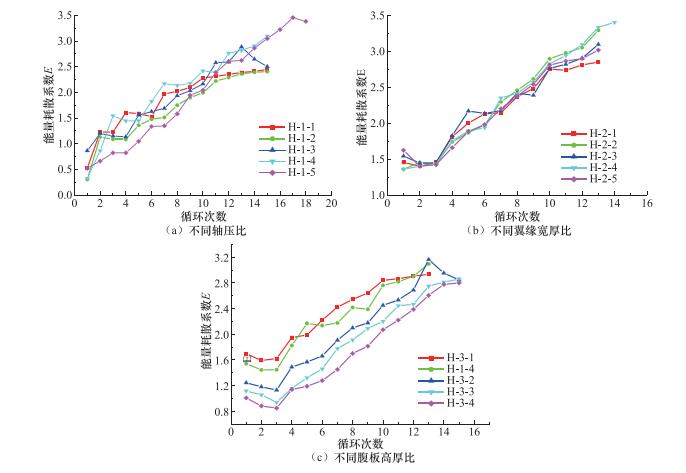
摘要: 为了进一步完善Q460钢材在抗震设计规范中相关限值的要求,本文利用有限元软件ABAQUS,以轴压比、翼缘宽厚比、腹板高厚比和壁板宽厚比为变量,建立了共48根“工”字型框架柱和“箱”型框架柱,分析了其抗震性能。结果表明:翼缘宽厚比对框架柱的能量耗散系数影响较小;能量耗散系数随轴压比、腹板高厚比(“工”字型)和壁板宽厚比(“箱”型)增大而明显减小;框架柱的极限承载力随轴压比的减小及壁板宽厚比和翼缘宽厚比的增大而逐渐增大,当腹板高厚比接近规范限值时,承载力下降趋势明显增大。与采用Q235钢材的框架柱相比,Q460钢材框架柱的延性较小,仅为2左右;当采用Q460钢材时,“工”字型框架柱的极限位移角限值建议取为0.03,“箱”型框架柱的极限位移角限值建议取为0.032。规范中对翼缘宽厚比限值的规定偏于保守,其值最大可取至9。无论是“工”字型框架柱还是“箱”型框架柱,其腹板高厚比均不宜过大。Q460钢材框架柱的刚度退化率随轴压比的增大而增强,且翼缘宽厚比越大,腹板高厚比越小,柱的初始刚度越大,刚度退化程度越明显。Abstract: In order to confirm the requirement of Q460 steel in seismic design better, the finite element software ABAQUS is used to simulate the seismic resistance of I-type and box-type bending members, with different axial compression ratios, flange width-to-thickness ratios, web height-to-thickness ratios and wall width-to-thickness ratio, under low cyclic repeated loading. The results showed that the difference in energy dissipation coefficient is not obvious for the members with different flange width-to-thickness ratio. The energy dissipation coefficient significantly reduces as the increase of the axial compression ratio, the web height-to-thickness ratio (I-type) and the wall width-to-thickness ratio (box-type). The ultimate bearing capacity of the specimens increases with the decrease of the axial compression ratio and the increase of width-thickness ratio of wall and flange. With the ratio of the web height-to-thickness approaches the standard limit, the downward trend of the bearing capacity exacerbates significantly. The ductility coefficient of Q235 steel column can reach 4, and that of Q460 steel column is only about 2. For the ultimate displacement angle of Q460 steel column, it is recommended to adopt 0.03 for the I-type column and 0.032 for the box-type column. In Chinese standard, the limit of the flange width-to-thickness ratio is conservative, and the value may be up to 9. The web height-to-thickness ratio should not be too large. The degree of stiffness degradation of Q460 steel column exacerbates with the increase of the axial compression ratio. The initial stiffness of the column is larger and the stiffness degradation is more severe when the flange width-to-thickness ratio increases and the ratio of the web height to thickness reduces.
-
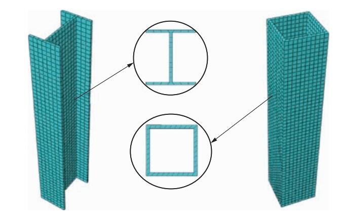
图 3 “工”字型柱、“箱”型柱网格划分
Figure 3. Division diagram of I-type column and box-type column grid
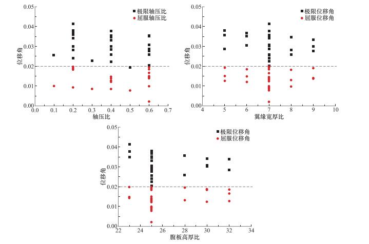
图 16 “工”字型柱位移角的统计结果
Figure 16. Statistical results of displacement angle of I-type column

图 17 “箱”型柱位移角的统计结果
Figure 17. Statistical results of displacement angle of box-type column
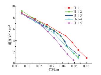
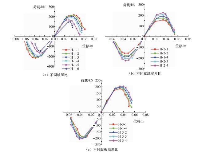
图 18 “工”字型柱不同轴压比对应的刚度退化
Figure 18. Stiffness degradation of I-type column under different axial compression ratios
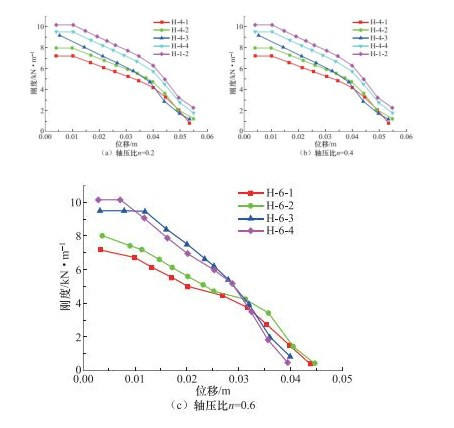
图 19 “工”字型柱不同翼缘宽厚比对应的刚度退化
Figure 19. Stiffness degradation of I-type column under different flange width-thickness ratio
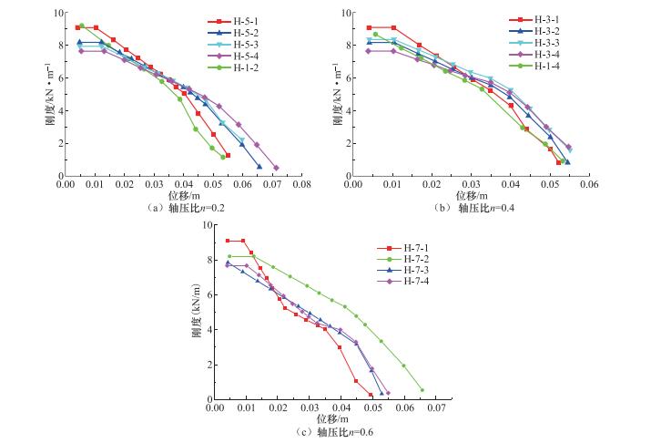
图 20 “工”字型柱不同腹板高厚比对应的刚度退化
Figure 20. Stiffness degradation of I-type column under different web thickness ratio
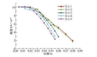
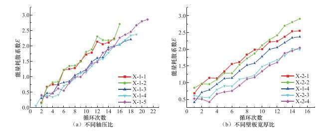
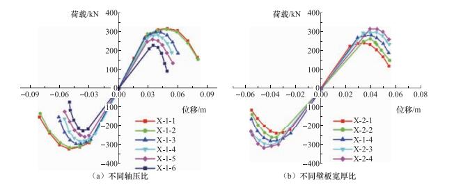
图 21 “箱”型柱不同轴压比对应刚度退化
Figure 21. Stiffness degradation of box-type column under different axial compression ratios
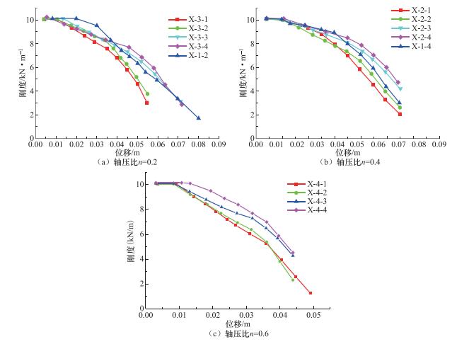
图 22 “箱”型柱不同壁板宽厚比对应刚度退化
Figure 22. Stiffness degradation of box-type column under different panel wide heavy ratios
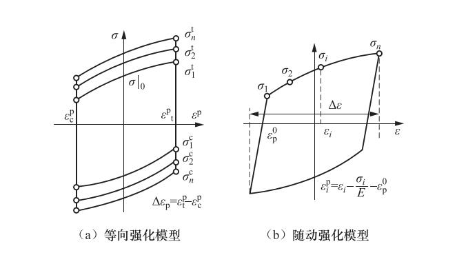
表 1 钢材本构模型参数
Table 1. Steel constitutive model parameters
钢材材性 $\sigma \left| {_0} \right.$/ N·mm-2 ${C_{{\rm{k}},1}}$/ N·mm-2 ${\gamma _1}$ ${C_{{\rm{k}},2}}$/ N·mm-2 ${\gamma _2}$ ${C_{{\rm{k}},3}}$/ N·mm-2 ${\gamma _3}$ ${C_{{\rm{k}},4}}$/ N·mm-2 ${\gamma _4}$ Q460 474 4797 156 3794 145 1498 107 Q345 429 7993 175 6773 116 2854 34 1450 29 Q235 407 6013 173 5024 120 3026 32 990 35  下载: 导出CSV
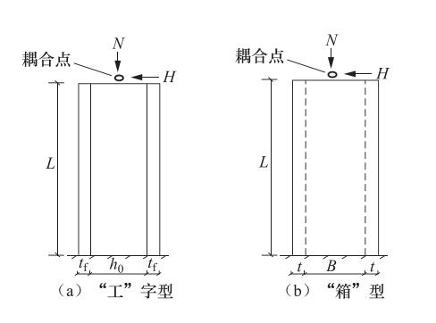
表 2 试件参数
Table 2. Test piece parameters
试件编号 H/mm B/mm tf/mm tw/mm b/tf h0/tw [b/tf] [h0/tw] n N/kN H-0-1 200 150 12 10 5.8 17.6 7.1 30.7 0.2 493.1 H-0-2 300 180 12 10 7.1 27.6 7.1 30.7 0.2 651.4 H-0-3 300 220 12 10 8.8 27.6 7.1 30.7 0.2 739.7
下载: 导出CSV
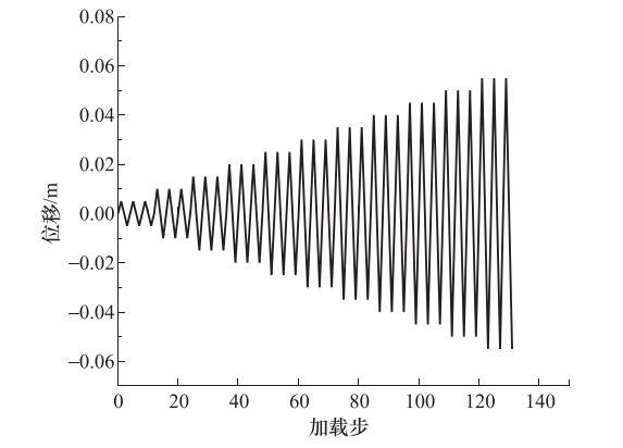
表 3 试件的位移荷载
Table 3. Displacement load of specimen
试件编号 ${\delta _1}$/mm ${\delta _2}$/mm ${\delta _3}$/mm ${\delta _4}$/mm ${\delta _5}$/mm ${\delta _6}$/mm ${\delta _7}$/mm H-0-1 9 18 36 54 72 90 108 H-0-2 6 12 24 36 48 60 72 H-0-3 6 12 24 36 48 60 72
下载: 导出CSV
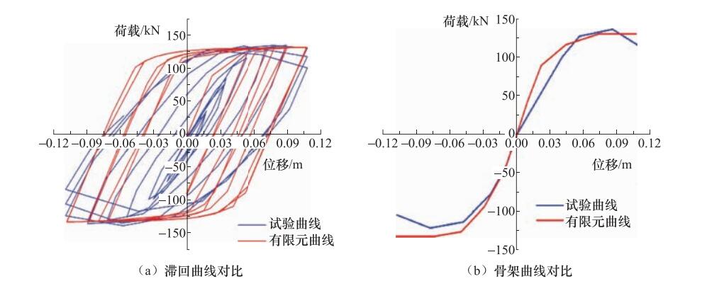
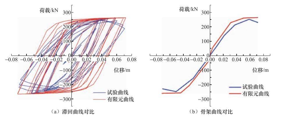
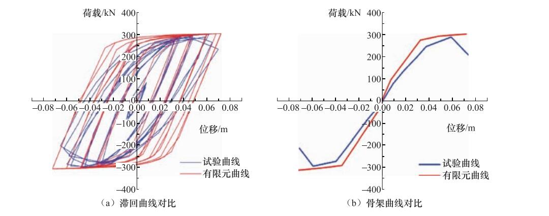
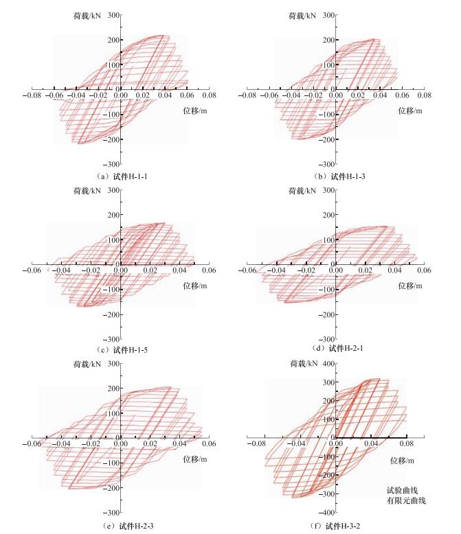
表 4 ABAQUS计算与试验结果的最大承载力对比
Table 4. Comparison of maximum bearing capacity between calculation and test
构件编号 ABAQUS结果/kN 试验结果/kN 相差/% H-0-1 132 139 -5 H-0-2 232 222 5.1 H-0-3 305 294 3.7
下载: 导出CSV
表 5 “工”字型截面试件设计参数
Table 5. Design parameters of I-type specimen
试件编号 b/mm h0/mm tw/mm tf/mm b/tf h0/tw λ L/mm n N/N H-1-1 178 250 10 12 7 25 30 1213 0.1 311.5 H-1-2 178 250 10 12 7 25 30 1213 0.2 623.0 H-1-3 178 250 10 12 7 25 30 1213 0.3 934.5 H-1-4 178 250 10 12 7 25 30 1213 0.4 1246.0 H-1-5 178 250 10 12 7 25 30 1213 0.5 1557.6 H-1-6 178 250 10 12 7 25 30 1213 0.6 1869.1 H-2-1 130 250 10 12 5 25 30 1183 0.4 1034.1 H-2-2 154 250 10 12 6 25 30 1199 0.4 1140.1 H-2-3 202 250 10 12 8 25 30 1224 0.4 1352.0 H-2-4 226 250 10 12 9 25 30 1234 0.4 1458.0 H-3-1 178 230 10 12 7 23 30 1088 0.4 1209.2 H-3-2 178 280 10 12 7 28 30 1700 0.4 1301.2 H-3-3 178 300 10 12 7 30 30 1524 0.4 1338.0 H-3-4 178 320 10 12 7 32 30 1648 0.4 1374.8 H-4-1 130 250 10 12 5 25 30 1183 0.2 517.0 H-4-2 154 250 10 12 6 25 30 1199 0.2 570.0 H-4-3 202 250 10 12 8 25 30 1524 0.2 676.0 H-4-4 226 250 10 12 9 25 30 1534 0.2 729.0 H-5-1 178 230 10 12 7 23 30 1088 0.2 604.6 H-5-2 178 280 10 12 7 28 30 1400 0.2 650.6 H-5-3 178 300 10 12 7 30 30 1524 0.2 669.0 H-5-4 178 320 10 12 7 32 30 1648 0.2 687.4 H-6-1 130 250 10 12 5 25 30 1183 0.6 1551.1 H-6-2 154 250 10 12 6 25 30 1199 0.6 1710.1 H-6-3 202 250 10 12 8 25 30 1224 0.6 2028.0 H-6-4 226 250 10 12 9 25 30 1234 0.6 2187.0 H-7-1 178 230 10 12 7 23 30 1088 0.6 1813.9 H-7-2 178 280 10 12 7 28 30 1400 0.6 1951.9 H-7-3 178 300 10 12 7 30 30 1524 0.6 2007.1 H-7-4 178 320 10 12 7 32 30 1648 0.6 2062.3
下载: 导出CSV
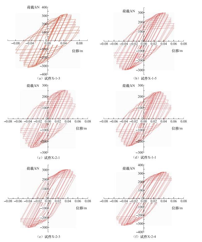
表 6 “箱”型截面试件设计参数
Table 6. Designing parameters of box-type specimen
试件编号 B/mm D/mm t/mm B/t [B/t] λ L/mm n N/N X-1-1 300 300 20 15 23.6 30 1573 0.1 533.6 X-1-2 300 300 20 15 23.6 30 1573 0.2 1067.2 X-1-3 300 300 20 15 23.6 30 1573 0.3 1600.8 X-1-4 300 300 20 15 23.6 30 1573 0.4 2134.4 X-1-5 300 300 20 15 23.6 30 1573 0.5 2668 X-1-6 300 300 20 15 23.6 30 1573 0.6 3201.6 X-2-1 260 260 20 13 23.6 30 1288 0.4 1840 X-2-2 280 280 20 14 23.6 30 1430 0.4 1987.2 X-2-3 320 320 20 16 23.6 30 1716 0.4 2281.6 X-2-4 340 340 20 17 23.6 30 1859 0.4 2428.8 X-3-1 260 260 20 13 23.6 30 1288 0.2 920 X-3-2 280 280 20 14 23.6 30 1430 0.2 993.6 X-3-3 320 320 20 16 23.6 30 1716 0.2 1140.8 X-3-4 340 340 20 17 23.6 30 1859 0.2 1214.4 X-4-1 260 260 20 13 23.6 30 1288 0.6 2760 X-4-2 280 280 20 14 23.6 30 1430 0.6 2980.8 X-4-3 320 320 20 16 23.6 30 1716 0.6 3422.4 X-4-4 340 340 20 17 23.6 30 1859 0.6 3643.2
下载: 导出CSV
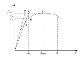
表 7 试件延性比计算结果
Table 7. Ductility ratio result of specimen from calculation
截面形状 试件编号 延性比 试件编号 延性比 试件编号 延性比 “工”字型 H-1-1 2.5256 H-3-1 2.5495 H-5-3 1.8175 H-1-2 2.5596 H-3-2 1.9412 H-5-4 1.8245 H-1-3 2.6382 H-3-3 2.4116 H-6-1 1.9092 H-1-4 2.5034 H-3-4 2.2301 H-6-2 2.0477 H-1-5 2.4784 H-4-1 1.9758 H-6-3 2.6084 H-1-6 1.3040 H-4-2 1.9735 H-6-4 1.9906 H-2-1 2.8007 H-4-3 1.5396 H-7-1 2.4463 H-2-2 2.8804 H-4-4 1.5725 H-7-2 1.8307 H-2-3 2.6508 H-5-1 2.0780 H-7-3 1.6720 H-2-4 2.3611 H-5-2 1.8176 H-7-4 1.7206 “箱”型 X-1-1 2.8794 X-2-1 2.4012 X-3-3 1.9370 X-1-2 2.7504 X-2-2 1.6506 X-3-4 1.8464 X-1-3 2.4262 X-2-3 1.8997 X-4-1 2.0211 X-1-4 2.1488 X-2-4 1.6812 X-4-2 1.8577 X-1-5 2.0218 X-3-1 2.0817 X-4-3 1.6825 X-1-6 1.6233 X-3-2 2.1513 X-4-4 1.9984
下载: 导出CSV
表 8 “工”字型柱位移角取值
Table 8. The recommended value of displacement angle of I-type column
n ${b_1}/{t_{\rm{f}}} \le 7\;且\;{h_0}/{t_{\rm{w}}} \le 28$ ${b_1}/{t_{\rm{f}}} > 7\;且\;{h_0}/{t_{\rm{w}}} > 28$ n≤0.2 θ>0.035 0.035≥θ≥0.03 0.2<n≤0.4 0.0375≥θ≥0.0325 0.035≥θ≥0.03 0.4<n≤0.6 0.0325≥θ≥0.0275 0.03≥θ≥0.025 n>0.6 0.03≥θ≥0.0275 0.0275≥θ≥0.025
下载: 导出CSV
表 9 “箱”型柱层间位移角的取值
Table 9. The recommended value of displacement angle of box-type column
n $B/t \le 15$ $B/t > 15$ n ≤0.2 θ>0.035 0.035≥θ≥0.04 0.2<n ≤0.4 0.04≥θ≥0.035 0.035≥θ≥0.03 0.4<n ≤0.6 0.035≥θ≥0.03 0.03≥θ≥0.025 n>0.6 0.03≥θ≥0.025 0.025≥θ≥0.02
下载: 导出CSV
-
班慧勇, 施刚, 刘钊等, 2011.Q420等边角钢轴压杆整体稳定性能试验研究.建筑结构学报, 32(2):60-67, 112. http://d.old.wanfangdata.com.cn/Periodical/jzjgxb201102009 郭子雄, 吕西林, 2004.高轴压比框架柱恢复力模型试验研究.土木工程学报, 37(5):32-38. http://d.old.wanfangdata.com.cn/Periodical/tmgcxb200405005 李国强, 王彦博, 陈素文等, 2013.Q460C高强度钢柱滞回性能有限元分析.建筑结构学报, 34(3):87-92. http://d.old.wanfangdata.com.cn/Periodical/jzjgxb201303011 施刚, 邓春森, 班慧勇等, 2012.Q460高强度钢材工字性压弯构件抗震性能的试验研究.土木工程学报, 45(9):53-61. 施刚, 邓春森等, 2012.Q460高强度钢材工形压弯构件抗震性能的试验研究.土木工程学报, 10(4):28-38. 王萌, 2013.强烈地震作用下钢框架的损伤退化行为.北京: 清华大学. 王萌, 石永久, 王元清, 2013.考虑累积损伤退化的钢材等效本构模型研究.建筑结构学报, 34(10):73-83. http://d.old.wanfangdata.com.cn/Periodical/jzjgxb201310009 中华人民共和国住房和城乡建设部, 中华人民共和国国家质量监督检验检疫总局, 2010.GB 50011-2010建筑抗震设计规范(附条文说明)(2016年版).北京: 中国建筑工业出版社. Chaboche J. L., 1986. Time-independent constitutive theories for cyclic plasticity. International Journal of Plasticity, 2(2):149-188. doi: 10.1016/0749-6419(86)90010-0 Fukumoto Y., Kusama H., 1985. Local instability tests of plate elements under cyclic uniaxial loading. Journal of Structural Engineering, 111(5):1051-1067. doi: 10.1061/(ASCE)0733-9445(1985)111:5(1051) 国际桥梁与结构工程协会.高性能钢材在钢结构中的应用.中国建筑工业出版社, 2010. Rasmussen K. J. R., Hancock G. J., 1992. Plate slenderness limits for high strength steel sections. Journal of Constructional Steel Research, 23(1-3):73-96. doi: 10.1016/0143-974X(92)90037-F Rasmussen K. J. R., Hancock G. J., 1995. Tests of high strength steel columns. Journal of Constructional Steel Research, 34(1):27-52. doi: 10.1016/0143-974X(95)97296-A Usami T., Fukumoto Y., 1984. Welded box compression members. Journal of Structural Engineering, 110(10):2457-2470. doi: 10.1061/(ASCE)0733-9445(1984)110:10(2457) -

 点击查看大图

计量
- 文章访问数: 161
- HTML全文浏览量: 44
- PDF下载量: 5
- 被引次数: 0
