
High Level Seismic Qualification Test of High Voltage Porcelain Insulator Disconnector in Chile High Earthquake Intensity Area
-
摘要: 为获取户外高压隔离开关的动态特性、研究瓷瓶破断力与地震载荷的关系以及验证隔离开关的抗震性能,开展了相关的考核试验。依据IEEE 693—2005标准的要求,试验前进行了应变计的校准试验、瓷瓶的弯曲破断试验和隔离开关的抗震性能试验。经过抗震试验,隔离开关完好无损且在抗震试验前后其共振频率变化不大,瓷瓶破断力大于地震载荷的2倍。结果表明隔离开关结构稳定,通过了抗震考核。Abstract: In order to obtain the dynamic characteristics of the outdoor high voltage disconnector and the relationship between the breaking force of the porcelain insulator and the earthquake load, and to verify the seismic performance of the disconnector, the calibration test of the strain gauge is carried out before the seismic test, the bending breaking test of the porcelain insulator is carried out on the basis of the requirements of the IEEE 693—2005 standard. Then the seismic performance test of the disconnector is conducted. After seismic testing, the disconnector is intact, and the resonance frequency of the porcelain insulator does not changed before and after the seismic test. The breaking force of the porcelain insulator is 2 times greater than that of the earthquake load. The result shows that the structure of the disconnector is stable to bear the seismic assessment.
-
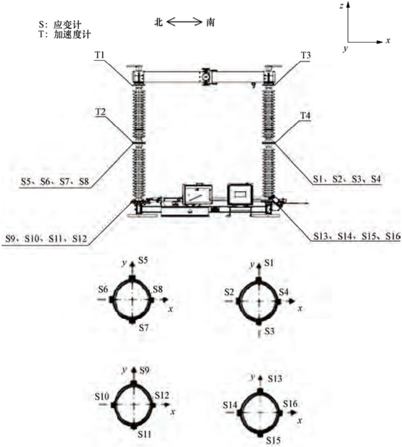
图 1 样件总装图和应变片位置示意图
Figure 1. General assembly drawing of specimen and diagram of strain gauge position
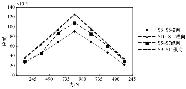
图 2 瓷柱1纵向和横向力-应变校验图
Figure 2. Force and strain check diagram of porcelain column 1 in longitudinal and lateral direction
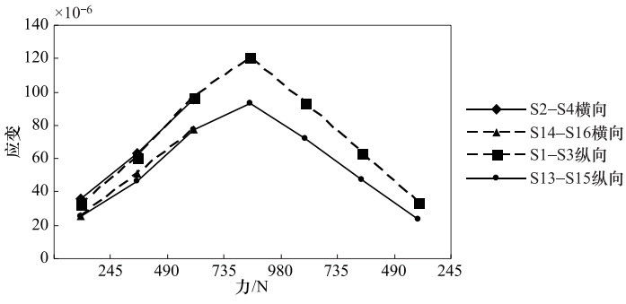
图 3 瓷柱2纵向和横向力-应变校验图
Figure 3. Force and strain check diagram of porcelain column 2 in longitudinal and lateral direction
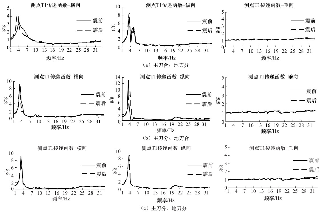
图 7 抗震试验前、后测点T1的传递函数对比
Figure 7. Comparison of transfer function of T1 at three points before and after seismic test
表 1 样件参数
Table 1. Parameters of specimen
型号 额定电压 额定短时耐受电流 额定频率 额定电流 质量 GW4C-252D(G·W)/J4000-50 252kV 50kA 50Hz,60Hz 4000A 650kg  下载: 导出CSV
表 2 力-应变测量结果
Table 2. Results of force and strain measurements
施加力/N 应变×10-6 S1—S3 S2—S4 S5—S7 S6—S8 S9—S11 S10—S12 S13—S15 S14—S16 245 25.16 25.16 29.15 26.21 35.07 36.19 32.12 35.77 490 45.75 50.58 45.92 46.48 63.00 65.06 59.89 62.41 735 76.44 76.29 86.32 68.88 92.62 94.45 95.41 94.45 980 92.00 95.60 108.51 91.38 125.33 125.15 119.51 119.12 735 71.07 85.60 69.75 95.98 94.85 92.52 490 47.04 60.43 46.81 63.85 64.26 62.56 245 23.51 29.65 22.33 34.61 31.44 33.06
下载: 导出CSV
表 3 瓷瓶绝缘子支柱样品的破断力
Table 3. Fracture force of the pillar sample of porcelain insulator
样品编号 1 2 3 4 5 6 7 8 破断力Fi/kN 10.71 9.95 11.57 10.86 10.49 9.13 11.12 9.65
下载: 导出CSV
表 4 主刀合、地刀分状态下振动响应探查结果
Table 4. The first order resonance frequency from vibration response detecting with the main cutter on and the ground cutter off
方向 一阶共振频率/Hz 测点T1 测点T2 测点T3 测点T4 横向 3.5 3.5 3.0 3.0 纵向 3.5 3.5 3.5 3.5 垂向 >33 >33 >33 >33
下载: 导出CSV
表 5 主刀分、地刀合状态下振动响应探查结果
Table 5. The first order resonance frequency from vibration response detecting with the main cutter off and the ground cutter on
方向 一阶共振频率/Hz 测点T1 测点T2 测点T3 测点T4 横向 3.5 3.5 3.5 3.5 纵向 3.5 3.5 3.0 3.0 垂向 >33 >33 >33 >33
下载: 导出CSV
表 6 主刀分、地刀分状态下振动响应探查结果
Table 6. The first order resonance frequency from vibration response detecting before seismic when the main cutter off and the ground cutter off
方向 一阶共振频率/Hz 测点T1 测点T2 测点T3 测点T4 横向 3.5 3.5 3.0 3.0 纵向 3.5 3.5 3.5 3.5 垂向 >33 >33 >33 >33
下载: 导出CSV
表 7 RRS考核试验过程中应变试验值
Table 7. Strain value in the process of RRS test
抗震考核试验 状态 应变×10-6 S1—S3 S2—S4 S5—S7 S6—S8 S9—S11 S10—S12 S13—S15 S14—S16 RRS1 主刀合、地刀分 62.90 109.34 65.60 87.11 130.95 168.98 159.85 176.66 RRS2 主刀分、地刀合 139.9 111.63 174.67 102.67 180.44 193.11 233.60 190.15 RRS3 主刀分、地刀分 99.83 116.71 169.71 102.66 165.25 184.20 170.38 186.64
下载: 导出CSV
表 8 RRS考核试验过程中加速度测量值
Table 8. The acceleration measurement value during the RRS assessment test
抗震考核试验 TT加速度/g T1加速度/g T2加速度/g T3加速度/g T4加速度/g X轴 Y轴 Z轴 X轴 Y轴 Z轴 X轴 Y轴 Z轴 X轴 Y轴 Z轴 X轴 Y轴 Z轴 RRS1 0.583 0.605 0.449 2.031 1.522 0.629 1.694 0.904 0.527 1.647 1.738 0.628 1.636 1.035 0.528 RRS2 0.587 0.633 0.426 1.756 2.069 0.566 1.064 1.678 0.507 2.063 1.939 0.563 1.236 1.537 0.592 RRS3 0.581 0.604 0.445 1.857 1.778 0.505 1.012 1.625 0.482 1.869 1.783 0.507 1.041 1.670 0.475 注:TT为台面加速度。
下载: 导出CSV
表 9 RRS考核试验中坐标轴的相关系数
Table 9. Correlation coefficient of three coordinate axes in RRS assessment test
抗震考核试验 相关系数 X-Y轴 Y-Z轴 Z-X轴 RRS1 0.007 0.059 0.085 RRS2 0.007 0.059 0.085 RRS3 0.007 0.059 0.085
下载: 导出CSV
表 10 试后主刀合、地刀分状态下振动响应探查
Table 10. The first order resonance frequency from vibration response detecting after seismic with the main cutter on and the ground cutter off
方向 一阶共振频率/Hz 测点T1 测点T2 测点T3 测点T4 横向 3.0 3.0 3.0 3.0 纵向 3.5 3.5 3.5 3.5 垂向 >33 >33 >33 >33
下载: 导出CSV
表 11 试后主刀分、地刀合状态下振动响应探查
Table 11. The first order resonance frequency from vibration response detecting after seismic with the main cutter off and the ground cutter on
方向 一阶共振频率/Hz 测点T1 测点T2 测点T3 测点T4 横向 3.0 3.0 3.0 3.0 纵向 3.5 3.5 3.5 3.5 垂向 >33 >33 >33 >33
下载: 导出CSV
表 12 试后主刀分、地刀分状态下振动响应探查
Table 12. The first order resonance frequency from vibration response detecting after seismic with the main cutter off and the ground cutter off
方向 一阶共振频率/Hz 测点T1 测点T2 测点T3 测点T4 横向 3.0 3.0 3.0 3.0 纵向 3.5 3.5 3.5 3.5 垂向 >33 >33 >33 >33
下载: 导出CSV
表 13 地震载荷计算
Table 13. Calculation of seismic load
抗震试验 S1—S3和S2—S4中
应变较大者×10-6相应地震载荷
FS/NS5—S7和S6—S8中
应变较大者×10-6相应地震载荷
FS/NRRS1 109.34(S2—S4) 897 87.11(S6—S8) 936 RRS2 139.9(S1—S3) 1491 174.6(S5—S7) 1578 RRS3 116.71(S2—S4) 1196 169.7(S5—S7) 1533
下载: 导出CSV
表 14 瓷瓶绝缘子支柱样品的破断力(kN)
Table 14. Fracture force of the pillar sample of porcelain insulator (kN)
样品编号 破断力${F_i}$ 平均值$\bar F$ ${F_i} - \bar F$ ${({F_i} - \bar F)^2}$ 标准差$\sigma = \sqrt {\frac{{\sum {{{\left({{F_i} - \bar F} \right)}^2}} }}{{i - 1}}} $ 1 10.71 10.435 0.275 0.075 0.807 2 9.95 -0.485 0.235 3 11.57 1.135 1.29 4 10.86 0.425 0.180 5 10.49 10.435 0.055 0.003 0.807 6 9.13 -1.305 1.70 7 11.12 0.685 0.470 8 9.65 -0.785 0.616
下载: 导出CSV
表 15 K值与样品数关系
Table 15. The relation between the K-value and the number of the samples
样品数i 1 3 10 K值 0.66 0.8 1
下载: 导出CSV
-
国家核安全局, 1995. HAF·J0053-1995核设备抗震鉴定试验指南.北京:中国标准出版社. 韩军科, 朱全军, 杨风利等, 2008.基底隔震高压隔离开关抗震性能分析.电力建设, 29(6):39-42. doi: 10.3969/j.issn.1000-7229.2008.06.011 黄峰, 吕建国, 朱祝兵等, 2010.基于ANSYS的GW7-252隔离开关抗震减震性能分析.科技导报, 28(20):52-57. http://d.old.wanfangdata.com.cn/Periodical/kjdb201020012 金松安, 刘朝丰, 武胜斌等, 2013.高海拔隔离开关抗震分析研究.高压电器, 49(10):37-45. http://www.wanfangdata.com.cn/details/detail.do?_type=perio&id=gydq201310007 吕宝龙, 2007.高压隔离开关抗震可靠性研究.上海: 上海大学. http://www.wanfangdata.com.cn/details/detail.do?_type=degree&id=Y1149662 人民网, 2014.我国遥感卫星为智利地震监测提供服务.(2014-04-10). http://world.people.com.cn/n/2014/0410/c157278-24871427.html. 搜狐新闻, 2015.智利发生8.3级强震或出现危险海啸.(2015-09-17). http://news.sohu.com/20150917/n421334133.shtml. 王海菠, 程永锋, 孙宇晗等, 2018.特高压气体绝缘开关设备瓷套管抗震性能研究.地震工程学报, 40(3):406-412. doi: 10.3969/j.issn.1000-0844.2018.03.406 谢强, 朱瑞元, 周勇等, 2012. 220kV隔离开关地震模拟振动台试验.电网技术, 36(9):262-267. http://d.old.wanfangdata.com.cn/Periodical/dwjs201209044 新华网, 2010.智利地震死亡人数升至799人.(2010-03-04). http://news.sina.com.cn/w/2010-03-04/024019782435.shtml. 中华人民共和国国家质量监督检验检疫总局, 中国国家标准化管理委员会, 2010. GB/T 13540-2009高压开关设备和控制设备的抗震要求.北京:中国标准出版社. 中华人民共和国住房和城乡建设部, 2010. GB 50556-2010工业企业电气设备抗震设计规范.北京:中国计划出版社. 中华人民共和国住房和城乡建设部, 2013. GB 50260-2013电力设施抗震设计规范.北京:中国计划出版社. 朱全军, 高政国, 陈应禄等, 2018.基于随机反应谱理论的支柱类电气设备抗震性能评估方法研究.地震工程与工程振动, 38(2):194-200. http://d.old.wanfangdata.com.cn/Conference/9449584 IEEE, 2006. IEEE 693-2005 IEEE recommended practice for seismic design of substations. New York:IEEE. -

 点击查看大图
计量
- 文章访问数: 242
- HTML全文浏览量: 77
- PDF下载量: 7
- 被引次数: 0
