Comparison of Four Simplified Analytical Methods for Seismic Design of Underground Structures
-
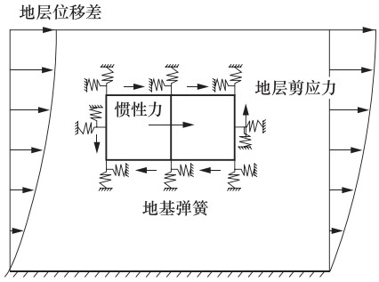
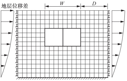
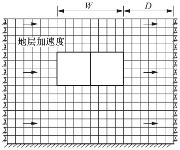
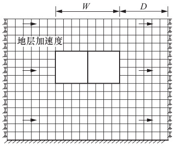
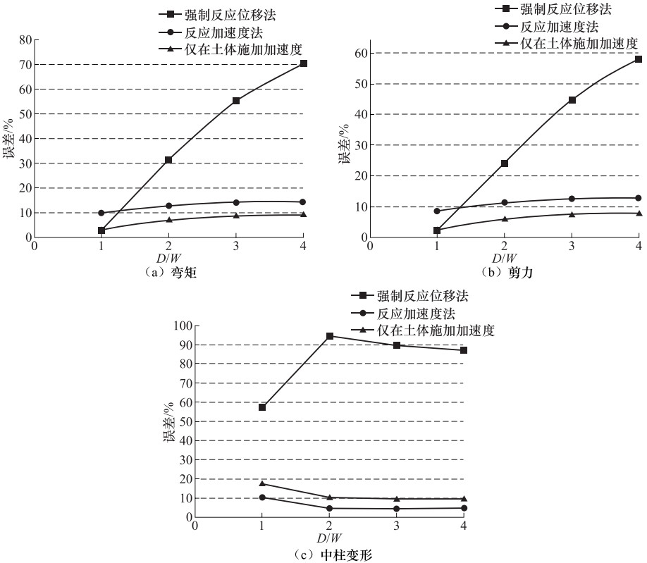
摘要: 在地下结构抗震设计简化分析方法中,强制反应位移法将土层变形施加在有限元模型侧边界模拟地震作用,反应加速度法将土层加速度施加到整个有限元模型上模拟地震作用,此外还有仅将土层加速度施加到土层模型上模拟地震作用的方法。上述方法均规避了反应位移法中关于弹簧刚度的取值问题,提高了计算效率。本文以1个双跨箱形结构为例,用动力时程分析的计算结果作为校核,分析了强制反应位移法、反应加速度法和仅将土层加速度施加到土体中的简化分析方法在不同侧边距条件下的计算精度,再结合常用的反应位移法,对比分析了4种简化分析方法的误差。分析结果表明:使用强制反应位移法时,侧边距取为1倍结构宽度导致的误差最小,反应加速度法和仅在土体施加加速度的简化方法对侧边距取值不敏感,反应位移法在角点造成的误差最大。Abstract: The theoretical basis of the simplified analytical method for seismic design of underground structure is that the deformation of underground structure depends on the deformation of foundation soil during earthquake, which fails to reflect the dynamic characteristics of the structure. Based on the most commonly used seismic displacement method, three kinds of simplified analytical methods are discussed in this paper. The forced displacement method is by applying the ground deformation to the boundary of the soil finite element model to simulate seismic load. The response acceleration method is by applying the ground acceleration to the integral finite element model to simulate seismic load. The third method is only by applying the ground acceleration to the soil finite element model to simulate seismic load. The above three simplified analytical methods can avoid calculating the value of the spring stiffness and improve the computational efficiency. Taking a double-span box structure as example, the calculations by applying three kinds of simplified analytical methods above with different lateral margins are carried out, and the analysis results are verified with the results of the dynamic time history method to calculate precisions. Combined with seismic displacement method, the error of four kinds of the simplified analytical methods is compared. The results show that the lateral margin should be equal to structure width when using the forced displacement method, and the response acceleration method and the method with only soil acceleration are not sensitive to the value of the lateral margin, and the error caused by the seismic displacement method reaches the maximum at the corner.
-
表 1 土体与结构的物理力学参数
Table 1. Physical and mechanical parameters of soil and structure
类型 密度/g·cm-3 弹性模量/MPa 泊松比 内摩擦角/° 粘聚力/kPa 土体 1.9 30 0.3 30 30 结构 2.3 30000 0.167 表 2 不同侧边距的弯矩计算结果
Table 2. Bending moment of structure with different lateral margins
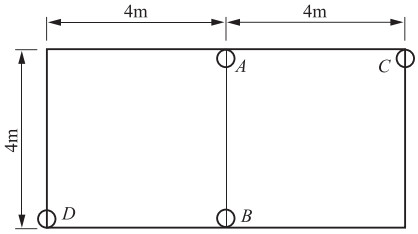
D/W 使用方法 弯矩/kN·m 截面A 截面B 截面C 截面D 1倍 强制反应位移法 292.9 -291.3 280.8 353.9 反应加速度法 319.4 -324.5 294.0 367.1 仅在土体施加加速度 296.5 -300.6 278.4 351.8 2倍 强制反应位移法 179.5 -181.3 200.7 282.1 反应加速度法 328.1 -33.3 301.0 372.2 仅在土体施加加速度 309.3 -313.6 287.9 360.0 3倍 强制反应位移法 100.4 -101.3 147.7 224.7 反应加速度法 331.7 -336.9 303.8 374.9 仅在土体施加加速度 314.5 -18.9 291.8 363.9 4倍 强制反应位移法 50.2 -50.4 113.8 187.4 反应加速度法 332.6 -37.8 304.3 375.5 仅在土体施加加速度 316.2 -20.6 292.8 365.0 反应位移法 286.5 -290.1 201.0 199.8 动力分析 282.5 -89.1 272.3 345.2 表 3 不同侧边距的剪力计算结果
Table 3. Shear force of structure with different lateral margins
D/W 使用方法 剪力/kN 截面A 截面B 截面C 截面D 1倍 强制反应位移法 -182.6 -182.6 -213.5 -263.8 反应加速度法 -195.8 -204.0 -205.6 -271.7 仅在土体施加加速度 -186.6 -186.6 -196.8 -266.3 2倍 强制反应位移法 -112.8 -112.8 -169.0 -249.3 反应加速度法 -201.3 -209.4 -210.0 -274.3 仅在土体施加加速度 -194.7 -194.7 -202.0 -270.7 3倍 强制反应位移法 -63.0 -63.0 -144.4 -219.7 反应加速度法 -203.6 -211.7 -211.9 -276.2 仅在土体施加加速度 -198.0 -198.0 -204.2 -273.3 4倍 强制反应位移法 -31.4 -31.4 -128.2 -199.6 反应加速度法 -204.1 -212.3 -212.0 -276.4 仅在土体施加加速度 -199.0 -199.0 -204.5 -273.8 反应位移法 -174.8 -183.0 -106.2 -106.2 动力分析 -175.7 -180.6 -194.0 -266.7 表 4 不同侧边距的结构变形计算结果
Table 4. Deformation of structure with different lateral margins
D/W 使用方法 中柱顶、底相对位移/mm 1倍 强制反应位移法 2.396 反应加速度法 5.011 仅在土体施加加速度 4.636 2倍 强制反应位移法 0.302 反应加速度法 5.340 仅在土体施加加速度 5.026 3倍 强制反应位移法 0.584 反应加速度法 5.354 仅在土体施加加速度 5.071 4倍 强制反应位移法 0.722 反应加速度法 5.346 仅在土体施加加速度 5.077 反应位移法 3.628 动力分析 5.596 表 5 Kobe波下弯矩计算结果
Table 5. Bending moment calculation results of structure under Kobe seismic wave
使用方法 弯矩/kN·m 平均误差/% 截面A 截面B 截面C 截面D 动力分析 375.3 -383.7 332.1 410.6 反应位移法 400.2 -403.7 284.3 276.0 10.5 强制反应位移法 298.8 -310.4 275.9 364.3 18.0 反应加速度法 341.9 -349.2 308.4 384.7 8.0 仅在土体施加加速度 312.4 -317.7 288.0 364.5 15.0 表 6 Kobe波下剪力计算结果
Table 6. Shear force calculation results of structure under Kobe seismic wave
使用方法 剪力/kN 平均误差/% 截面A 截面B 截面C 截面D 动力分析 -230.8 -242.9 -218.3 -299.0 反应位移法 -242.6 -257.5 -159.9 -139.9 13.7 强制反应位移法 -190.4 -190.4 -180.2 -290.7 27.0 反应加速度法 -207.4 -222.2 -209.8 -281.2 4.4 仅在土体施加加速度 -196.9 -196.9 -198.1 -275.4 5.6 表 7 Kobe波下结构变形计算结果
Table 7. Deformation calculation results of structure under Kobe seismic wave
使用方法 中柱顶、底相对位移/mm 平均误差/% 动力分析 5.808 反应位移法 4.768 17.9 强制反应位移法 3.232 44.4 反应加速度法 5.371 7.5 仅在土体施加加速度 4.900 15.6 -
陈国兴, 陈苏, 杜修力等, 2016.城市地下结构抗震研究进展.防灾减灾工程学报, 36(1):1-23. http://d.old.wanfangdata.com.cn/Periodical/jzgcjsysj2018063865 陈晓强, 钱七虎, 2010.我国城市地下空间综合管理的探讨.地下空间与工程学报, 6(4):666-671. http://d.old.wanfangdata.com.cn/Periodical/dxkj201004002 川岛一彦, 1994.地下构筑物の耐震设计.日本:鹿岛出版会. 林皋, 1990a.地下结构抗震分析综述(上).世界地震工程, (2):1-10. http://www.wanfangdata.com.cn/details/detail.do?_type=perio&id=QK000004586861 林皋, 1990b.地下结构抗震分析综述(下).世界地震工程, (3):1-10, 42. http://d.old.wanfangdata.com.cn/Periodical/dbdzyj201201005 刘晶波, 刘祥庆, 李彬, 2008.地下结构抗震分析与设计的Pushover分析方法.土木工程学报, 41(4):73-80. doi: 10.3321/j.issn:1000-131X.2008.04.011 刘晶波, 王文晖, 赵冬冬等, 2013.地下结构抗震分析的整体式反应位移法.岩石力学与工程学报, 32(8):1618-1624. http://d.old.wanfangdata.com.cn/Periodical/yslxygcxb201308014 刘如山, 胡少卿, 石宏彬, 2007.地下结构抗震计算中拟静力法的地震荷载施加方法研究.岩土工程学报, 29(2):237-242. doi: 10.3321/j.issn:1000-4548.2007.02.014 片山幾夫, 足立正信, 嶋田穰等, 1985.地下埋設構造物の実用的な準動的解析手法「応答震度法」の提案.土木学会年次学術講演会講演概要集, (40):737-738. 钱七虎, 2017.推进城市地下空间规划建设的思考.城乡建设, (18):60-65. doi: 10.3969/j.issn.1002-8455.2017.18.024 权登州, 王毅红, 井彦林等, 2015.黄土地区地铁地下结构抗震研究综述.震灾防御技术, 10(3):565-574. http://zzfy.eq-j.cn/zzfyjs/ch/reader/view_abstract.aspx?flag=1&file_no=20150310&journal_id=zzfyjs 同济大学, 2009.DG/TJ 08-2064-2009地下铁道建筑结构抗震设计规范.上海: 上海市建筑建材业市场管理总站. 杨智勇, 黄宏伟, 张冬梅等, 2012.盾构隧道抗震分析的静力推覆方法.岩土力学, 33(5):1381-1388. doi: 10.3969/j.issn.1000-7598.2012.05.016 中华人民共和国建设部, 2006.GB 50111-2006铁路工程抗震设计规范.北京:中国计划出版社. 中华人民共和国住房和城乡建设部, 2014.GB 50909-2014城市轨道交通结构抗震设计规范.北京:中国计划出版社. Hashash Y. M. A., Hook J. J., Schmidt B., et al., 2001. Seismic design and analysis of underground structures. Tunnelling and Underground Space Technology, 16(4):247-293. doi: 10.1016/S0886-7798(01)00051-7 Iida H., Hiroto T., Yoshida N., et al., 1996. Damage to daikai subway station. Soils and Foundations, 36(S):283-300. Penzien J., 2000. Seismically induced racking of tunnel linings. Earthquake Engineering Structural Dynamics, 29(5):683-691. doi: 10.1002/(ISSN)1096-9845 Tateishi A., 2005. A study on seismic analysis methods in the cross section of underground structures using static finite element method. Structural Engineering, 22(1):41-53. doi: 10.2208/jsceseee.22.41s Wang J. N., 1993. Seismic design of tunnels:a simple state-of-the-art design approach. New York:Parsons Brinckerhoff Quade and Douglas Inc. -


 下载:
下载:
